3.12.2014

GPSd, Java, and the Raspberry Pi

The float for RoboGoby will have a Global Positioning System, or GPS, onboard for real-time tracking. GPSs are readily available and extremely easy to interface into your project. There are various different GPS module from Sparkfun, Adafruit, Mouser, and other distributors. They come with different antennas, although a custom fit ceramic antenna is the most common.

Ceramic antenna

GPSs also come with different update rates (in Hz) and different channels. Channels represent the number of satellites a receiver can receive data from at the same time. And Hz, or hertz, is the speed of your module. If you're not sure which GPS is right for your project, check out SparkFun's GPS Buying Guide

The awesome thing about GPS receivers is that soon after they receive power, they continuously output a string of ASCII characters through a serial cable/UART connection. The string contains coordinates, altitude, time, speed, directional degrees, etc.  In order to read the data from a GPS you need to download a GPS parser which can decode the GPS ASCII and then implement in your code (in our case a simple Java program). 

We are currently using a pre-constructed USB GPS (image below -- you can see the ceramic antenna inside). Other GPSs (like the Ultimate GPS from Adafruit) can be wired to an Arduino or Pi using UART (more info found here).


USB GPS Reciever


To test the GPS, we used a generic python setup from Adafruit (found here). The following quick steps make sure the GPS is working (our USB GPS was located on /dev/ttyUSB0). After making sure the GPS is working, you can add the python code, gps.txt file, and Java code we used to read the GPS data (we had to write the data to a file using python and then read it using Java. Although this means switching platforms it is ten-fold easier than using Java directly -- trust us, we tried).


If you type in the following you will see a bunch of unknown characters. This is because the Pi cannot decipher the ASCII strings. You'll need to download GPSd to do that.


1. Download GPSd and the python library needed to read GPS data:


2. Tell GPSd where to look on the Pi for the data stream (in our case /dev/ttyUSB0)


3. Make sure that your GPS is using GPSd and receiving data from your module:

GPS Data


...and using the same cat command above you now see recognizable data (somewhat recognizable...)!


The next step is parsing the data into a usable form. For this, we are going to use Java. (make sure you have Java installed ---> sudo apt-get install openjdk-7-jre). The Java code will read the data written to a text file using Python. The python code uses the TPV-Class to read the lat and lon data (check out the link for the full set of data available using TPV).

All of the code can be found in the GPS folder located on our download site. Below is a quick explanation of what the code does.

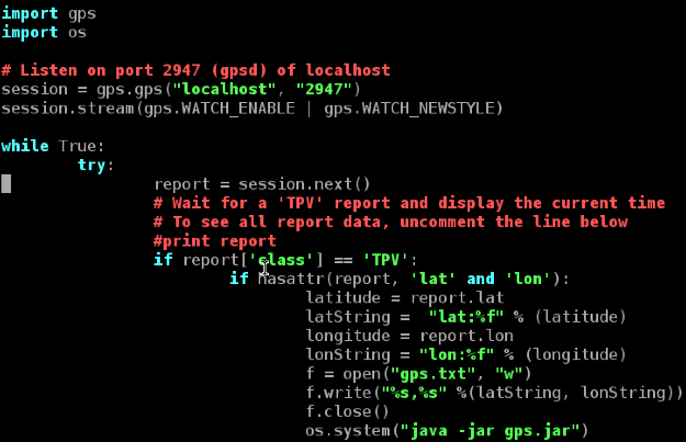
1. The python code (gpsPi.py) reads the data from the GPS and parses it into recognizable latitude and longitude values. It then writes this data to gps.txt and then immediately runs gps.jar. The Java file (gps.jar) reads the data from gps.txt and converts it into a DD°MM.M'SS.SSS" format. Pictures of the code are below:

***do not name your python file gps.py as the method it uses to call the GPS module will NOT work.


gpsPi.py

gps.jar


…and this is the data output on the Pi!


To make sure your coordinates are correct check out this sweet website.

2.18.2014

Waterproofing a Tru-Stability Pressure Sensor w/ Arduino

Our spooling mechanism is going to unspool/spool our tether based on the depth of the submersible (+/- a margin of error). Therefore, as part of the float we need to design a depth sensor capable of traveling up to 250 feet underwater (roughly 105 psi). After much searching, we settled on using Honeywell's Tru-Stability Force Sensor to do this. We purchased the SSC 150psi model with a 5v logic and analog output. Below is a quick example of how to use the Tru-Stability Sensor, which is followed with how we waterproofed the sensor. This is the data-sheet we used.

SSC 150 psi


1. Hook up the Sensor using the 5v, A0, and Ground pins. Our sensor is pictured below. The pin-out is also pictured (analog version -- Table 9). If you have a different sensor just use this data sheet to find the drawing of your sensor and the tables below to find the correct pin-out.

SSC 150PSI (take note of pin locations)

Sensor Pin-Outs


2. Upload the SSC150.ino sketch located in the "SSC150" folder here. The code is based off of the data table and equations found on Page 6 of the data sheet (and pictured below). A shout of to a forum post (which I have sadly lost...) which mentioned the equation needed to calculate pressure.


B.N. -- Our sensor is based off of 5v logic


3. Upload the sketch to your Arduino to make sure it's working. If you are around 1 atm (sea level) the PSI should read around 14.70, the feet around 0.00.

B.N -- This sketch does not currently calibrate itself when powered. This is because our submersible might lose power 250 feet underwater and we don't want the sensor to automatically calibrate when rebooted at that depth. Therefore, in the finished product there will be a specific boot sequence to run through before using the submersible.


4. We then chose a sturdy PVC pipe drilled some holes, added the sensor (with soldered wire extensions), and siliconed everything to waterproof the connections.


We then had an issue deciding on how to have the sensor measure pressure. Should we use a homemade manometer or a balloon to sense the variation in pressure? What about a flexible latex covering? PSI increases in increments around .4 psi/foot of H20  and because our submersibles tether is going to be based on depth, we needed a setup which gave us the most accurate readings. In the end we decided on using a manometer because we were able to read a large enough pressure difference per foot.

The sensor is siliconed to a tube which exits the PVC and is exposed to the water. Our sensor was sealed to this small diameter tube. Not water can enter the tube when submerged because of the cohesions of the water and the fact that one end of the tube is sealed As the sensor descends, the water pressure increases the air pressure in the tube. Below is a picture of the finished sensor:


Sensor w/tube

Finished sensor

I tested this sensor at the local pool with my sister (thanks Mackie L.!). We attached it to the top of a weight a dropped it roughly 3.8 feet (4 feet minus the width of the weight). Below are the readings from the sensor and a picture of it in the pool (H2 in the Arduino code should be H20).


Pressure submerged in pool


Sensor at 3.81 feet


Although this setup worked, it still needs to be tested to depths up to 250 feet in salt water. Hopefully it will continue to work, but you never know. Stay updated for more posts about completing the float!

2.02.2014

I2C: Raspberry Pi, Arduino, and Pi4j

After realizing that we may need multiple sensors (ie. pressure sensor) and micro-controllers (ie. Arduinos) attached to our Raspberry Pi's in the submersible, we decided to try other types of communication. After reading through articles dedicated to different communication protocols, we eventually chose to use I2C (i-squared-c) communication. I2C stands for Inter-Intergrated Circuit and is a type of serial bus (for more detailed information check out Wikipedia).

This communication protocol is used for easy, three wire connection between devices. The bus is comprised of Ground, SDA (Serial Data Line), and SCL (Serial Clock Line). The master node on the bus generates a clock and initiates the communication with the slave. Likewise, the slave node receives the clock and responds when addressed by the master. In our case, the Arduino is the slave while the Raspberry Pi is the master.


Software:

Hardware:
  • Raspberry Pi Rev B
  • Arduino Uno and Arduino Mega
  • Connector cables


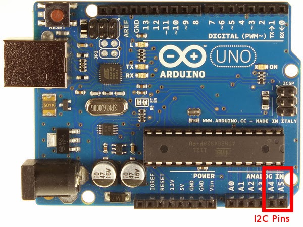
The setup used in this tutorial connects the Raspberry Pi and an Arduino on an I2C bus. Below is an image of the SDA and SCL pins on the Raspberry Pi's GPIO setup and Arduino Uno (A4 & A5):


After connecting the correct pins (don't forget ground!), setup i2c between the Pi and Arduino using these quick steps:


1. Comment out (#) the i2c option (and SPI too) on the Pi's blacklist:


2.  Add i2c to /dev/modules


3. Now you can download the i2c-tools needed for debugging:


4. Finally, make sure to add "pi" to the user list unless you want to run your commands using SUDO.


5. Add the .jar files found on Pi4J's download page to the Pi's Java PATH (this will allow you to run the file using java -jar) and as an external library in Eclipse. To add pi4j-core.jar to your Pi, move it from its temporary location to the following location (/usr/lib/jvm..../lib):


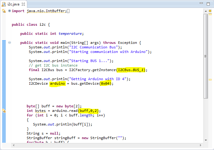
6. Download the Java code pictured below. The code can be found in the folder mentioned in the software section above. The highlighted sections below show that the Pi first joins the i2c bus, then locates the Arduino with address 4, and finally reads a set buffer of size 2 from the "slave". For more information on the specific Pi4J methods and implementation check out this site.


7. You are now finished loading the i2c kernel on the Raspberry Pi. Upload the code from the folder in the downloads sections (.ino file), although the code below is complete and ready for use.


8. Attach the Arduino to power and type in the following command on the Pi. You should see this table below. The Arduino should be recognized as the 0x04 device on the bus (the command for the RevA RPi would switch from a 1 to  0 after -y).


9. Finally, run the .jar file called i2c-temp.jar on the Raspberry Pi (this file will reads two bytes from the Arduino). You will see the same two bytes on the Pi 's terminal. These should be the same numbers you send from the Arduino. An image of the result is below (please disregard the J5 at the bottom of the image):


As we said above, i2c communication not only has the benefit of using only three wires, but it is  able to connect more than 127 devices to the Pi at once.


=============
The Arduino code used above will be modified in the future to transfer depth, temperature, and various other readings to the Pi using this circuitry. Please note that Pi4J using the Arduino as a slave  on the i2c bus is far from perfect – we ran into many problems testing this over the past week. Some of our findings (inadequacies) can be found in the Arduino (.ino) file on the downloads page we provided above.

1.27.2014

First Media Appearances

In the past three weeks we appeared in the local news twice. First in the newspaper and second on WSCH6, our local news broadcasting center.

Larry Grard, from the Tri-Town Weekly, interviewed us after school just before Christmas break. He then wrote an article that was published on Wednesday January 8th. The online version of the article can be found here.


After the article ran WSCH6 contacted us and expressed interest in interviewing us as well. Tim Goff, from WSCH6, came and talked with us on Thursday, January 16. The story aired the next day at both 6:00pm and 11:00pm as well as on Saturday, January 18 at 10:30. The video and a write up done by WSCH6 can be found here.


Clip from video

1.26.2014

Maya Animations

We decided to make an animation of the submersible in maya so that people could get an idea of what the end product might look like or do. The first attempt was not very successful as we were working with parts of maya that we hadn't used before.

The First Attempt:

We used the one body submarine because it seems that that is going to be our final choice. We started by creating a sea floor, then added in the submarine and a camera (with aim).

Two lights were used, one directional light aimed downward from above the scene, and a spot light that went on the from of the submersible. The first was not very bright, and only existed so that the sub and "unlit" part of the scene could be seen. The main light went on the front of our sub as a spot light because that is how the submersible will actually be seeing; after a few meters there is very little light and so the submersible will have to provide its own.

As with any photorealistic rendering we then spent a fair amount of time making the submersible, rocks, and sea floor look natural and life like.

After animating the scene (just the sub and camera) a few different times we decided that it looked quite boring and we added in an arc shaped rock and a smaller rock on the sea floor.

Finally we decided that we wanted to add in seaweed. To do this we used the "squirrel fur" option in the furs menu. We then changed it to be long, green, and more sparse than actual fur. Also we made it scraggly and have a much thinner top than bottom so it would look more seaweed like.

Finally we made a fan that affected the fur, through a hair system. And animated the seaweed so that it waved back and forth like waves washing over them.

Finished First Attempt Unrendered


Then came the hardest part of trying to make a video from the animation. We rendered 96 frames as iffs to start off, but were unable to find a converter. Then we realized that with QuickTime 7 Pro we could convert jpegs into a .mov.

Once we did that we decided that we needed to make it longer and had to fix some of the lighting. Thus we turned it into 144 frame animation and re-rendered a few times, and tried converting a few times until we finally got it to work.

This is the final animation at 12fps

The Second Attempt:

This past Monday (1/12/14) we learned that we were being interviewed for Channel 6 on Thursday. We decided that the more basic animation was not going to be good enough for television and so decided to make a better one.

We then decided to make a better version of the animation, and in the next four evening spent a total of about 24 man hours on it.

We first took the new SolidWorks model of the submarine that Jon Amory helped us to create. It has the main thruster as well as a flashlight and pi camera on top of the basic shape. 

Possible Final Submersible

The first thing that we did was locate the preset that takes place underwater. It was hard to find and we had to resort to using the find function on the computer. It was very helpful though as there was a light that made it look like anything put into the scene had water moving over it, and it had fog that reduces visibility in the distance.

We then created the squirrel fur seaweed and the rock again. Then we worked on making the submarine and rocks look realistic. 

Then made the light for the front of the submarine and made it part of a group.

Then we did the actual animating of the submarine and the camera (with aim), as well as the fan for the seaweeds motion. 

Then spent a fair amount of time getting a geyser that emits bubbles to be at the very end of the animation. As well as a mass of crystals, which were already in maya under PaintEffects. 

Finished Second Attempt Unrendered

Second Attempt Full Screen


Here is what the final animation looks like.

1.25.2014

RasPi Camera: GStreamer-1.0 w/ Windows 7

As talked about in our previous post, the MJPG-Streamer video rate using the Pi's Camera module was definitely not acceptable for our project. The maximum speed (with dropped frames)of raspistill was far below the video quality needed for our project. After researching multiple different streaming methods we settled on using GStreamer-1.0, an open source visual and audio streaming platform. This method is faster as the software opens up a direct network pipeline between the Raspberry Pi and the OCU (in this case a Windows 7 machine).

This tutorial is Windows 7 specific, but will work on Mac and Linux. The tutorials for Mac and Linux are actually much easier as GStreamer was originally created for those platforms.

1a. First prime the Pi by adding the follow to /etc/apt/sources.list:


2a. Then update the Pi to download dependencies for GStreamer:


3a. Finally download GStreamer-1.0:


4a. The download is complete. To pipe raspivid through GStreamer use the command below.


****Make sure to use this specific code because GStreamer-1.0 for Windows does NOT include gdpdepay or gdppay as plugins.


1b. In Windows, visit http://gstreamer.freedesktop.org/data/pkg/windows/1.2.2/ and download this (make sure you have the correct installer -- Windows 7 comes with a pre downloaded .msi installer, but other versions do not):


2b. Install!

3b. Using cd and dir navigate to /gstreamer/1.0/64_x86/bin


4b. Now you can use the get-launch-1.0.exe command to read the stream coming from the Pi (make sure to use the ip you found using ipconfig above!).


As you can see the quality of the stream is as good as the Pi Module can give. Unlike the jerky MJPG-Streamer, the GStreamer pipeline has <.3 seconds of delay!! This is perfect for our Pi-based submersible. Unfortunately, there is not yet a Java API built for GStreamer-1.0. We will be defaulting to the older version (GStreamer-.10) in order to use this video streaming software.


1.12.2014

RasPi Camera: MJPG-Streamer Comparison

After playing around with different USB webcams we decided to test out video hardware/software specifically made for the Raspberry Pi. Although having the ability to attach a USB cam to the Pi opens up many possibilities, our hope is to have a video platform which streams high definition video with the lowest possible latency. While USB cameras have a relatively nice picture, they have higher latency than we would like. Below is a quick run through on how we setup the Pi Camera and it tested against a USB camera using MJPG-Streamer

Pi Camera

We used the Pi Camera Module (found here). A picture of the module is below. To view the post where we got a lot of our information on the Pi Module check out this blog post: 


To attach this hardware find the black clasp near the Ethernet jack and pull up on the tabs. Take the ribbon cable on the module and slid it into the clasp (making sure that the wires on the clip and cable are touching). Now press down on the tabs. Done! The module is correctly attached to the Pi. A picture for reference is below: 


Next you need to enable the RasPi Camera from the Pi's configuration window. Do this by running:


And choosing this option in the configuration window:


After rebooting both update and upgrade the Pi:


To compare the streams we are going to test MJPG-Stream on the Pi Module and a USB webcam at the same time. We will not be testing the native streaming at this point because of a few disadvantages (ie. you must always be done before you tell the Pi where to stream video to). Use the links on this page to help you setup native streaming with the Raspberry Pi Camera Module. Otherwise, continue reading.

Next you have to install MJPG-Streamer. Documentation for this can be found on THIS post (or this very useful blog). After MJPG-Streamer is compiled you must make a file to which the RasPi video is copied to and then read from by MPJEG-Streamer.

First make a directory to which you can save the images:


Then make it writeable:


*****you must constantly created /tmp/stream and make it writeable or the stream will not work!

You now mush run a raspistill image capture at a very small interval. This is used for video because MJPG-Stream is only compatible with jpeg images and not the h264 video created by raspivid. The command below will have the stream capture every .1s: (for information on the meaning of these commands check out this blog post).


Then run MJPG-Streamer. MJPG-Streamer will both read the pic.jpg created by raspistill and write it to a web-server.


To log onto the webserver type in the <http://ip:port> into your web browser. In this case it is <http://port:9000>. Here is an image of what you should see: 


Comparision: USB and RasPi Module:


After setting up the Pi Camera module we tested it against using MJPG-Streamer and a USB webcam.

Pi Pros:
  • Small!
  • High quality
Pi Negs:
  • SLOWER
    • Easily backed up (skipping frames because it cannot write any faster than .1s


USB Pros:
  • Faster
  • Customizable
USB Negs:
  • Larger camera
  • Not as nice quality for the price

Conclusion:

We would recommend using a USB webcam for streaming live video from the Pi using MJPG-Streamer because of its fluidity compared to raspistill. The raspistill feature on the pi camera is meant for taking images and does not take them at a pace not fast enough for a robot. We have not given up on using the Pi Camera module though...stay tuned for a tutorial using the camera's native streaming software! Next time we'll compare the native streaming against MJPG-Streamer.