Showing posts with label Camera. Show all posts

7.05.2015

Camera & Front Sensor Mounts

Camera Mount:

The camera mount is made of four distinct pieces. There are two parts that hold the camera system in place, the servomotor motor mount and the bearing mount. The other two parts are the shaft and camera mount.

Below are the two side mounts. One side holds the servo motor and the other side acts as a bearing for the shaft which the camera is mounted to.

Servomotor Mount
Shaft Bearing Mount


We thought about putting a bushing in the hole instead of using the plastic support as a bearing, but we decided against it as the printer plastic is quite slick.


The third part is the shaft on which the camera rotates. The white piece on the end which attaches to the servo motor is a servo horn that comes packaged with the servo motor. The shaft has a large mount connected to it. This makes a "shaft extension" that has three main functions. First, it has holes which attach it to the white piece on the servo, holding the piece to the shaft. Second, the two holes on the bottom are to hold the camera case to the shaft. Third the four top holes and two half circles are a LIDAR mount (see below).

Shaft Side View

Shaft Isometric View

The final part of the camera mount is the camera case itself. The case will be filled with epoxy, which is why there is a front as it makes it easier to keep epoxy off of the lens. The hole in the top is for the USB cable, which we are using to communicate with the camera board. 

Camera Case


Integrated LIDAR Mount

Our front facing LIDAR is attached to the camera system so that they tilt in conjunction with each other. As mentioned above the mount is part of the camera shaft mount. It consists of four bolt holes to attach the sensor and two arcs for the circular "lenses" to rest on. 

LIDAR in Mount


Entire Camera & LIDAR Mount


--------------------------------------------------------------------------------------------------------------------------

UPDATE (7/13/2015): A New Camera Mount

After finalizing the design for out lighting system we needed to change a few things on the camera mount (but kept the sensor mount). Using the same basic idea we consolidated the pieces from the previous mount and cleaned things up a bit.

We kept the same basic design for the shaft mount as above, but added a camera case to it. While this definitely stressed the 3D printer to its maximum ability, we thought it was important for a simpler design. This piece is mounted to a rotating shaft (controlled by a servo) and then mounts to the front facing LiDAR, the stereoscopic camera, and the IR LEDs. It can be considered one of the most important parts of the sub design. An image of the mount is below:

Camera + LiDAR + LED Mount

The face piece to this design is also very important because it holds LED mounts. This piece is made out of Delrin for extra stability. The large holes in the plastic are for the cameras, the medium sizes holes are for 3mm bolts, and the small holes are for 2mm bolts. 

Cam Cover and LED Mount


We also changed the Servo Mount and the Shaft Bearing Mount. These new mounts were incorporated into the half-circular mounts that replaced the LED heat-sinks (changed with lighting design change). The updated mounts are pictured below. The one on the right is the servo mount as well as the right hand cover. The left has the shaft bushing and acts as the left side cover.


Then using these mounts and putting everything together we get the final assembly for the front of the sub:


Front Mounts&Sensors


As you can see this design not only has less pieces than the other design, but it looks much better overall.

--------------------------------------------------------------------------------------------------------------------------


Front Sensor Package

Just behind the camera and in front of the foremost thruster we put a pack of sensors. The pack consists of a depth sensor, an IMU and a downward facing LIDAR. The IMU is on the central axis of the sub and the depth sensor is just in front of it - there is also a track we will use to route wires. The hole and bolts for the LIDAR are on the left side of the sub (right side of the image). The LIDAR sticks out the bottom of the mount so that it is flush with the bottom of the submersible body.


Front Sensor Package

And this is a picture of both the camera mount and the sensor package mounted in the front of RoboGoby:

Camera and Sensor Mount


6.20.2015

Choosing a Camera – Update

The search for a camera to use in our robot has been long and involved. Throughout the process, we have worked toward finding a camera that satisfied a basic set of requirements. Our camera needs to be capable of outputting high quality video, interfacing with C++ or Java through the Beaglebone black, and be capable of stereoscopic imaging. We believe we have finally found a camera that can satisfy all of those requirements: the DUO MLX.
This camera, while expensive, boasts an impressive array of features and capabilities. It stereoscopic and infrared, allowing it to judge depth in low light environments. It comes equipped with a small array of programmable infrared LEDs and an on-board 9-DOF freedom IMU, allowing it to sense its orientation with a high degree of accuracy. Finally, it comes with a SDK which, just recently, allows it to interface with ARM based micro-controllers like the Beaglebone - although access to this capability requires subscription to DUO's developer program. This SDK is compatible with C++ and C, as well as Java through the Java Native Interface. Another distinct advantage of this camera is its form factor. It is very small, being only 52mm long. This will allow us to fit many more design features into the front portion of the submersible.

4.06.2014

Direct Network Connection: PC + PC + Raspberry Pi

After setting up the Ubiquiti wireless connection we needed a way of connecting the OCU (or PC in our case) to the Raspberry Pi. Although creating your own "network" seemed daunting at first, it ended up being extremely easy.

This post covers PC to PC and PC to Raspberry Pi connections. Before you start, you will need a cross-over cable or switch for the PC to PC connection. If you need to purchase a cable, they run for around $10 on Amazon. If you want to make your own cable, switch the wires as shown in this image below (which is stolen from a quick Google search). A switched cable works by switching the RX and TX signals between laptops/devices.


If you are connecting directly to your Pi, you do not need a crossed cable. Luckily the Linux machine is smart/user friendly enough to do the switching internally!

PC to PC:

1. First, purchase/make your own crossover cable or plug both PCs into a switch.
2. Configure your Ethernet sharing settings. To do this, navigate to Network and Sharing Settings on your PC. If you a are using a crossover/switch you'll be able to see the network as an Unidentified network. Click on the text that says Local Area Connection (highlighted in the picture below):


3. After clicking on Local Area Connection, click on Properties. Navigate to the Internet Protocol Version 4 and click on that. Finally enter your desired IP address. This address can be whatever you want (ie. 192.168.2.xxx)-- we chose to use the generic 192.168.x.xxx subnet. Remember the static IP address entered on computer one (in this case it's 192.168.2.2).


5. Next initialize the other PC. To do this open up the other computer. Navigate through the same pages mentioned above. Open the Internet Protocol Version 4  on the second laptop. Change the static IP address on this machine to match the subnet of the first computer. For us that means using the address 192.168.2.1. Restart both machines. You should now be able to ping back and forth using these static IP addresses!

**If this does not work you may have to modify your sharing settings (located in the advanced sharing settings option). This option is located on the left of the Network page.


PC to Raspberry Pi:

After following the steps above used to initialize the PC (with specified subnet above), connecting the Raspberry Pi is a piece of cake.

1. Connect the laptop to the Raspberry Pi using either a crossover cable or a regular Ethernet cable.
2. Either ssh onto or plug the Pi into a monitor. Edit the /etc/network/interfaces file using this command:


3. Create a static eth0 IP by configuring your network sharing settings as shown in the image below:


4. Reboot the Pi. Ping the Pi! Connect over SSH! You should now have a direct network connection between the Raspberry Pi and you PC.


By creating our own direct network connection with the Pi we are creating a simple option for communication with our submersible. Our finished product will use these static network settings to easily create a connection between the OCU and the submersible using Ubiquiti extenders.

4.02.2014

Wireless Bridge with Two Ubiquiti NanoBridge M5

In order to broadcast long-range wireless signal from the submersible's float to a land based computer or station, we purchased two Ubiquiti wireless bridges. So far, we have set up these stations in order to achieve data transfer between two computers over a short distance. We have yet to test them over long ranges or optimize them.

One of the Units:


Important Note: When using these bridges, or any bridge for that manner, to connect two computers directly for data transfer, it is necessary to connect the devise to the computer with something called a switched, or crossover, Ethernet cable. These cables have different wiring patterns that allow them to communicate directly between machines. They are not required on Mac computers as Mac hardware handles the switching. The crossover cables can be made, but they can also be bought for a relatively low price. If you wish to switch multiple devices together, you will need something called a switch, which is a hub for multiple Ethernet devices.

To set up our bridges, we used, in addition to the units, 4 Ethernet cables, 2 switched and two not. The switched cable is run from the computers Ethernet port to the LAN port on the POE injector for the bridge. To access the setting for the bridges, we followed the directions listed in the instruction book that came with the bridges. The only problematic step was setting the static IP address of the computers Ethernet port. On PC, this can be done by going to the network and sharing center, click on the "change adapter settings" options, select the Ethernet adapter, open its properties, double click on Internet Protocol Version 4, and select a manual IP address. Set this to something in the domain of 192.168.1.x, where x is between 1 and 100 (to keep it simple). These settings can be found in wireless settings on Mac.

To set up the point to point link between the two devices, once you have gotten into the settings for the wireless bridge, follow the instructions in this video. The hardware is slightly different but the steps are almost the same.

https://www.youtube.com/watch?v=__xzHnK6IVs

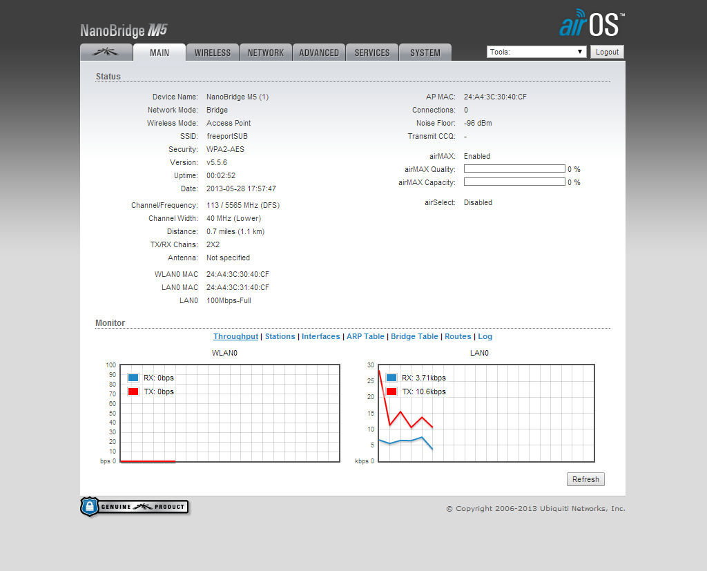
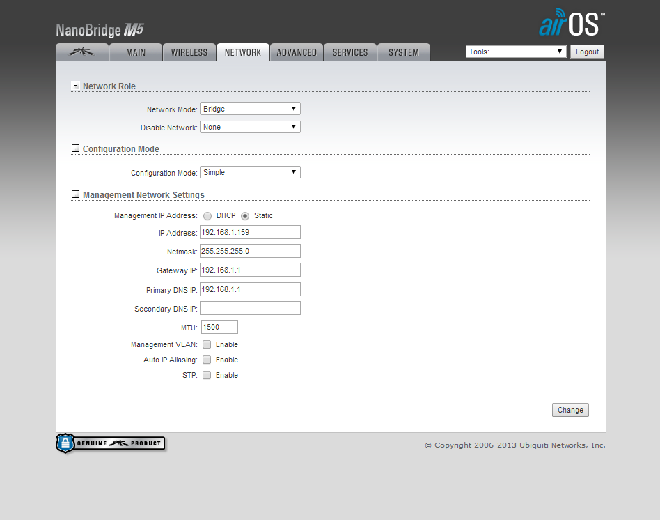
When you are done, your settings should look something like these:

Access Point:


Station:


If the two units show red status lights, then they are connected and the link is complete. Packets can be sent to the IP address of the opposite computers Ethernet port via the console command ping 192.168.1.x This should return data.

Our next post will show how we used this network connection to create a private network in order to communicate with the electronics on the submersible.

2.02.2014

I2C: Raspberry Pi, Arduino, and Pi4j

After realizing that we may need multiple sensors (ie. pressure sensor) and micro-controllers (ie. Arduinos) attached to our Raspberry Pi's in the submersible, we decided to try other types of communication. After reading through articles dedicated to different communication protocols, we eventually chose to use I2C (i-squared-c) communication. I2C stands for Inter-Intergrated Circuit and is a type of serial bus (for more detailed information check out Wikipedia).

This communication protocol is used for easy, three wire connection between devices. The bus is comprised of Ground, SDA (Serial Data Line), and SCL (Serial Clock Line). The master node on the bus generates a clock and initiates the communication with the slave. Likewise, the slave node receives the clock and responds when addressed by the master. In our case, the Arduino is the slave while the Raspberry Pi is the master.


Software:

Hardware:
  • Raspberry Pi Rev B
  • Arduino Uno and Arduino Mega
  • Connector cables


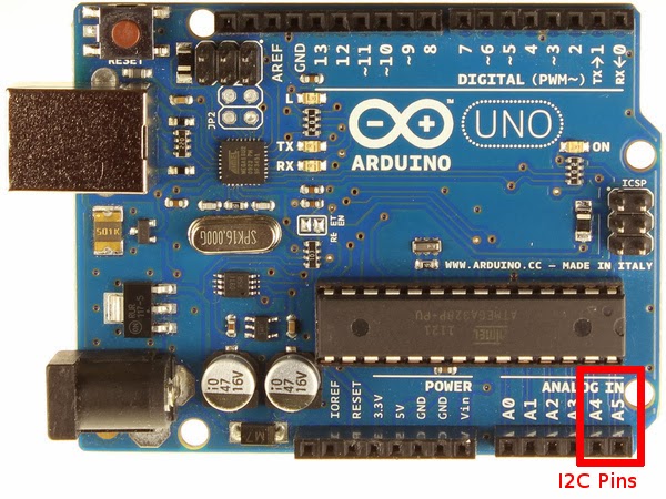
The setup used in this tutorial connects the Raspberry Pi and an Arduino on an I2C bus. Below is an image of the SDA and SCL pins on the Raspberry Pi's GPIO setup and Arduino Uno (A4 & A5):


After connecting the correct pins (don't forget ground!), setup i2c between the Pi and Arduino using these quick steps:


1. Comment out (#) the i2c option (and SPI too) on the Pi's blacklist:


2.  Add i2c to /dev/modules


3. Now you can download the i2c-tools needed for debugging:


4. Finally, make sure to add "pi" to the user list unless you want to run your commands using SUDO.


5. Add the .jar files found on Pi4J's download page to the Pi's Java PATH (this will allow you to run the file using java -jar) and as an external library in Eclipse. To add pi4j-core.jar to your Pi, move it from its temporary location to the following location (/usr/lib/jvm..../lib):


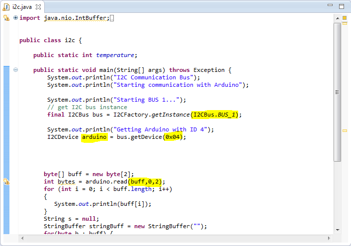
6. Download the Java code pictured below. The code can be found in the folder mentioned in the software section above. The highlighted sections below show that the Pi first joins the i2c bus, then locates the Arduino with address 4, and finally reads a set buffer of size 2 from the "slave". For more information on the specific Pi4J methods and implementation check out this site.


7. You are now finished loading the i2c kernel on the Raspberry Pi. Upload the code from the folder in the downloads sections (.ino file), although the code below is complete and ready for use.


8. Attach the Arduino to power and type in the following command on the Pi. You should see this table below. The Arduino should be recognized as the 0x04 device on the bus (the command for the RevA RPi would switch from a 1 to  0 after -y).


9. Finally, run the .jar file called i2c-temp.jar on the Raspberry Pi (this file will reads two bytes from the Arduino). You will see the same two bytes on the Pi 's terminal. These should be the same numbers you send from the Arduino. An image of the result is below (please disregard the J5 at the bottom of the image):


As we said above, i2c communication not only has the benefit of using only three wires, but it is  able to connect more than 127 devices to the Pi at once.


=============
The Arduino code used above will be modified in the future to transfer depth, temperature, and various other readings to the Pi using this circuitry. Please note that Pi4J using the Arduino as a slave  on the i2c bus is far from perfect – we ran into many problems testing this over the past week. Some of our findings (inadequacies) can be found in the Arduino (.ino) file on the downloads page we provided above.

1.25.2014

RasPi Camera: GStreamer-1.0 w/ Windows 7

As talked about in our previous post, the MJPG-Streamer video rate using the Pi's Camera module was definitely not acceptable for our project. The maximum speed (with dropped frames)of raspistill was far below the video quality needed for our project. After researching multiple different streaming methods we settled on using GStreamer-1.0, an open source visual and audio streaming platform. This method is faster as the software opens up a direct network pipeline between the Raspberry Pi and the OCU (in this case a Windows 7 machine).

This tutorial is Windows 7 specific, but will work on Mac and Linux. The tutorials for Mac and Linux are actually much easier as GStreamer was originally created for those platforms.

1a. First prime the Pi by adding the follow to /etc/apt/sources.list:


2a. Then update the Pi to download dependencies for GStreamer:


3a. Finally download GStreamer-1.0:


4a. The download is complete. To pipe raspivid through GStreamer use the command below.


****Make sure to use this specific code because GStreamer-1.0 for Windows does NOT include gdpdepay or gdppay as plugins.


1b. In Windows, visit http://gstreamer.freedesktop.org/data/pkg/windows/1.2.2/ and download this (make sure you have the correct installer -- Windows 7 comes with a pre downloaded .msi installer, but other versions do not):


2b. Install!

3b. Using cd and dir navigate to /gstreamer/1.0/64_x86/bin


4b. Now you can use the get-launch-1.0.exe command to read the stream coming from the Pi (make sure to use the ip you found using ipconfig above!).


As you can see the quality of the stream is as good as the Pi Module can give. Unlike the jerky MJPG-Streamer, the GStreamer pipeline has <.3 seconds of delay!! This is perfect for our Pi-based submersible. Unfortunately, there is not yet a Java API built for GStreamer-1.0. We will be defaulting to the older version (GStreamer-.10) in order to use this video streaming software.