Showing posts with label Prototype. Show all posts

8.24.2015

Front Assembly – Camera and Sensor Mounts

After designing our front camera and sensor mounts in SolidWorks, we moved onto prototyping and assembling the pieces. We designed all of the mounts to be 3D printed using the same Makerbot Replicator we used to print the thruster curtains and rear cone.

Camer Mount

Printing:


Our first couple of prints were test prints. We wanted to see if the printer could handle the complex camera mount and test the orientation of each of the side mounts. After a few re-designs we were able to print the final camera mount, but the side mounts continued to gives us problems. Due to their large footprint, the filament continued to peel off of the print plate.

After more than four unsuccessful attempts at printing the front camera mount we switched over to a different 3D printer. We used a Dremel 3D Printer with PLA. The printed turned out well, although getting the software to work was another story (lets just say it needed some persuasion).

Right Cover
Left Cover

Cover Pair


Assembly:


There are a few different aspects to the assembly of the Camera Mount. The assembly consisted of adding threaded inserts, painting the printed plastic, fitting the polycarbonate shield, and finally epoxy the camera and mounting it in the front. 


Threaded Inserts:

Similar to our posts about the through hole thrusters and the large rear thruster we used threaded inserts to mount many of our front pieces. The entire front assembly consisted of ten threaded inserts. Two M3 inserts were used to mount the servo on the right cover. Two M4 inserts were used in the camera cast to hold the camera cover on the camera. Two more M4s were used for the sensor mount. The last four M6 inserts on the left and right side coverts to hold them on the aluminum frame. To get a better understanding of the location of the inserts refer to the images at the bottom of this post. The holes colored red are where the inserts will be used. Below is a CAD drawing of the right cover:

Front Right w/ Threaded Inserts


Epoxying the Camera:

Similar to last year we decided to epoxy our camera. We epoxied the camera in order to waterproof it without having to design a watertight space in the front of the submersible. To epoxy the camera we mounted it to the camera cover using M2 bolts.


DUO w/o Epoxy

We then covered it in two layers of epoxy. The first layer was black heat-sink epoxy. We used this to ensure that the electronics on the camera board did not overheat. The second layer was optically clear epoxy. We used this to put some finishing touches on our first coat and to cover the built in LEDs  on the board.

Epoxying Camera


Mounting the Camera:

In order to mount the camera after it had dried we needed to do a few small things. First we mounted the servo to the right side cover using the M3 threaded inserts. We then used the servo horn that comes with the the servo and screwed it to the camera mount. Next we screwed the LED packages onto the camera cover and mounted all of that to the camera cover. We added a 1/4" Delrin rod to support the side of the camera opposite the servo. We did this by screwing it into the camera mount closest to the servo and sliding it through the entire mount.

Servo w/ Horn and Delrin Shaft

We also mounted the LiDAR to the top half of the camera mount. We use this for measuring distances in order to detect any objects in front of the submersible.

Mounted LiDAR

Sensor Mount

The sensor mount was a little less involved than the camera mount. After printing the mount (pictured below) we epoxied the LiDARs PCB and tested it.

Empty Sensor Mount

We then wired the MS5803 Pressure sensor and the Razor IMU. After finishing the with the wiring we used heat-sink epoxy to mount the electronics in the mount. We also added M4 threaded inserts to the mount in order to mount the LiDAR. Below is a picture of the finished sensor pack. You can see our down facing LiDAR as well as where the IMU and pressure sensor are epoxied in place.

Finished Sensor Pack

Assembly

After finishing both the sensor mouth and the camera mount we assembled it on the front of the sub. To assemble the front we first mounted the camera/servo combination to the right side cover. In the picture you can also see our LED units we will use for lighting.


Camera Mounted on Right Cover

Next we bent a piece of polycarbonate to fit in the slot in the printed plastic and pressed the left cover on. we then slid it inside our frame. The finished assembly is pictured below:

Finished Front Assembly

8.21.2015

Power Distribution and Tether

There are four important parts of the power in system in RoboGoby – the tether, a cord grip, a cable connector, and our power supply.

Power Supply

The power supply we're using for RoboGoby is a 12v 500W PC power supply. Specifically it is the Shuttle 500W power supply. This power supply is perfect for RoboGoby because it's maximum current draw matches up with the maximum current draw on our thrusters before cavitation.

The power supply has 3.3v, 5v, 12v, and -12v power rails. We only wanted the 12v rails on the power supply so we cleaned it up. We connected the green wire to ground, allowing the power supply to actually power up when plugged in. To organize the 12v wires, we removed the cover of the power supply (pictured below) and then cut all of the wires except a large group of yellow wires (12v rail) and black wires (ground). We used zip ties and heat shrink along with Ultra Plug Dean Connectors to organize the wires into two positive and negative plugs.

Open Power Supply (not finished)

Finished 12v Supply

Tether Cable

The tether is actually made up of two different wires. The first is a 100ft, 3 wire, 16AWG extension cable. The second is a 3ft, 3 wire, 14AWG power cable. Because we're using an AC power supply we decided to also use extension cable for our prototype. This allows us to plug in RoboGoby anywhere with a AC power. This makes testing easier as we don't have to carry around a battery pack and worry about DC-AC power inversion.

About 1 foot above the submersible the extension cable turns into the slightly larger 14AWG 3 wire tether. We went with 14AWG as this cable is so short that the extra size and weight is not a big deal and in the future we may want the entire tether to be 14AWG so larger amp draws would be possible.
Extension Cable


Cord Grip

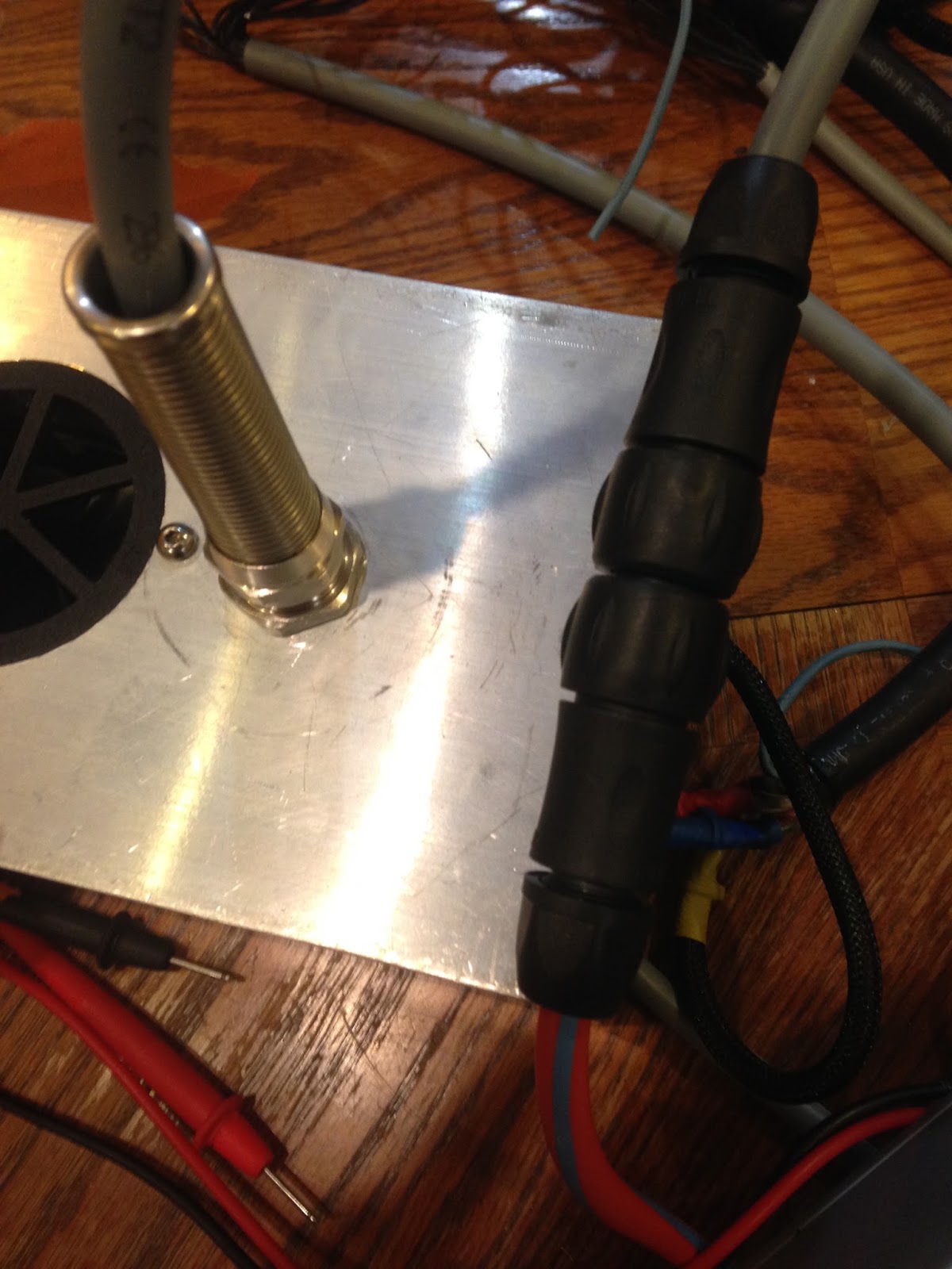
We used a cord grip very similar to the ones found on either end of our watertight compartment, which are described here. The only difference is that there is a short (~3") spring to provide support for the wire entering the cord grip.

Cord Grip w/Support

The cord grip makes sure that the tether is securely attached to the submersible – preventing any slippage – in a way that it both strong and easily removable in case we need to make changes.

Waterproof Connector

The waterproof connector is the one we described in this post. We decided to have a connector outside the submersible so that we could easily detach the sub from the tether, allowing for easier transport and more customizability.

Waterproof Connector

Though we were originally worried about how much force the connector could take, we have found that it holds up very well to the amount of tension it will experience. 

Tether and Connector

8.18.2015

Rear Thruster v2.0 – Building

Before reading this you should read about the CAD design for the rear thruster. As a brief into, the rear thruster body consist of 4 different parts: the nozzle, the fins to connect the nozzle, the cone, and the motor mount.

Cone

As described in this post the new rear cone design is larger than our previous cone. This caused a few issues in its manufacturing. We first tried to cut the cone out of a large 5"x6"x6" piece of polyethylene on a CNC machine that has a rotary axis. Unfortunately the piece weighed a bit to much and was very unwieldy so we had to try something else. Before we move on here is a picture from when we bored out the polyethylene bloc with a hole for the motor to sit in...it makes a flower!

Polyethylene "flower"

We decided to use the 3D printer instead (older version of MakerBot Replicator); surprisingly enough, it worked extremely well. You can see an image of the print with threaded inserts below, as well as a image of the cone inside the body to show how nicely it fits.

Cone w/ Inserts onto of Aluminum Body

Cone in Aluminum Body

Quick tip
We are printing this piece with the large flat side facing down. This is because it leaves only a little bit of overhang, which is not a problem for a printer with decent scaffolding. If your printer does not have that ability then, according to one of our advisers, adding a chamfer to the overhang should allow you to safely print the piece.

Motor Mount

The motor mount for the rear thruster was cut out of Delrin, the same material we used to make our small thruster mounts. This is a major improvement from last year as it gives us much more freedom while mounting the motor. Last year we used the small cross mount that comes with the Turnigy SK3 motor which we didn't like very much because it barely sticks out beyond the edge of the motor – meaning we had to have a very small compartment for the motor. This year we are able to have a larger compartment for the motor, which we wanted for cooling and flow purposes, as well as a much more secure connection to the rear cone.

The mount itself is a pretty simple piece. It has four holes near the middle for attaching the motor and four holes  around the edge for attaching the mount to the cone. The spokes are as large as we felt comfortable making them, while allowing for water flow but keeping enough strength to hold the motor in place.


Motor Mount


Motor on Mount

For information on the motor, shaft, and propellor that will be mounted to this check out our post on preparing the motors.

Nozzle

We kept the nozzle that was made last year in this year's prototype. We decided to do this because it is a hard part to manufacture, last years version came out nicely, and is still in good condition. It was printed in two parts and then melted/epoxied together and, finally, painted red.


Nozzle

Fins

We also used the Delrin plastic to make the fins that attached the cone and the nozzle. There are three fins, two of which are the same while the third is slightly different – the different sizes are needed because of the asymmetry of three fins in a four sided cone. 


Fins


Assembly

There were a few different tasks required to assemble the rear thruster. First we had to press the threaded inserts into the cone. We used threaded inserts to avoid cross threading and stripping our threads on the relatively weak PLA.

To press the threaded inserts into the printed PLA we heated them with a heat gun and easily pressed them into place. 

Two Threaded Inserts and Two Empty Holes

Using a Bolt to Install Threaded Inserts

We then epoxied the fins into the slots in the cone and nozzle to ensure a strong and lasting connection between the two. We also used the same epoxy mixed with acetone to create an epoxy paint. We then used this to paint the cone, getting ride of the shiny PLA look and giving it a smoother look.
Painting Cone w/ Epoxy

Painted Cone


Next we used epoxy to mount the nozzle onto the rear cone. After that we mounted the motor mount/motor to the cone using 12mm M4 bolts. And the thruster is complete (finally)! Below are a few profile shots and pictures of the finished thruster.

Rear Thruster Profile

8.13.2015

Cutting the Aluminum Frame

Once we had all of the thrusters finished we needed to cut out aluminum body. Using the 5"x5"x12" aluminum frames and CNC router we were able to cut all of the necessary holes on the frame of RoboGoby.

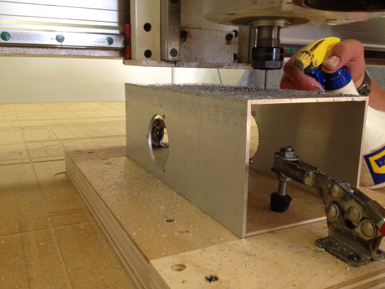
To cut the aluminum we used a Laguna CNC router. To ensure our aluminum was cut using the correct zero points we did two things. First, we created a pocketed jig that snuggly fit the aluminum frame. The jig was comprised of five wood pieces (four sides and a bottom) and two planar clamps. We framed the aluminum around the center of the bottom board and then used the planar clamps to hold the aluminum in place. The second thing we did to ensure our zero point was routing out a large section of the CNC table.  We cut a pocket that held the jig at the zero point we defined for it. We then screwed the jig in place and used the clamps to switch out the aluminum pieces. Below is a picture of the aluminum frame mounted in the jig which was then screwed to the table.

Cutting Aluminum w/ Jig


Due to the symmetry of our design, the opposing sides of the aluminum had the same cuts for the thrusters and for connecting the different sections. Each side of the submersible had at least four holes for mounting the thruster. The large holes fits our thruster grills and the three small holes are for M4 bolts. On top of these four holes, two of the four sides have four more holes (for a total of eight holes). These holes are for M6 bolts and will be used to attach either the front assembly, rear thruster, or a different aluminum section.

Four Holes

Eight Holes

After cutting out the aluminum we used a knife and de-burring tool to get rid of any sharp edges on the aluminum.

De-Burring


If you have been watching the blog closely you will have realized that a couple holes seem to be missing  – those for the downward facing LIDAR and the tether cord grip. We decided to wait on cutting these out until we're sure about the design. At the time we cut out the aluminum frame we were unsure of both.

After we had cut out the aluminum frame we decided to decided to cut the cord-grip hole using a drill press. We were able to get a relatively precise hole without the hassle (and time sink) of re-zeroing a CNC machine. We also purchased a 1/2"-14 NPT thread and thread the hole for the cord grip.

Hole for Tether


The final product looks quite nice and was manufactured using only 2D vector drawings, a CNC machine, and a few hours.

Isometric View of Rear Frame

8.10.2015

Watertight Compartment – Construction

After designing our watertight compartment we deferred most of the construction to professional machinists and welders. Our previous waterproof compartment post shows the three parts we need machined and also gives an idea of what the final product will look like. This post will give you an idea of how the parts look and fit together in real life.


Machined Parts

As mentioned above, we had three parts machined for the waterproof section. We can't tell you much about how they were made – only that they were cut out with a CNC Milling Machine. Darin Marion from Porter's Precision Machining made the parts for us. Below are pictures of each of the parts (reference this post for a cool "Idea to Finished Product" comparison!):

Plug Housing


Plug


Back End


Welding

After making the inserts for our aluminum frame we needed to have the parts welded in place. The plug housing and back end were welded to a 12inch section of our extruded aluminum body. Again, we had the welding done professionally. We used Cumberland Ironworks (in Pownal, Maine) who welded our parts within one day. Below is a picture of the welded midsection.

Welded Compartment

Assembly

The last thing we had to do was add all of our accessories. and assemble the compartment. We threaded on each of our cord grips and mounted the Presta Valve using Loctite. We also bent some chain to fit over two M6 bolts we designed threaded radially into the plug. These bolts and the chain give us a good handle for applying equal pressure to the entire plug. This makes it much easier for one person to pull the plug out on the fly. The pictures below show mounted cord grips, the finished plug, and an image of our plug/wire setup.

Cord Grips in Back End

Finished Plug

Plug w/ Wires and Chain

8.09.2015

Small Thrusters v2.0 – Building

Before reading this you should get acquainted with our design by reading about the CAD models for the small thrusters. As a brief intro, the small thruster is made up of four different parts: the grills, motor mount, thruster curtain, and curtain mount.

Grills

The grills are designed to keep large debris out of the small thrusters. Each thruster has two grills, one on each side of the thruster (to block both ends). We printed all of our grills on a MakerBot Replicator with PLA. The grill sits flat with the exterior of the sub and has 6x.125" spokes to stop material from getting caught in the 2" thruster.

Printed Grill


Motor Mount

The motor mount was cut out of .25" Delrin. Delrin's material properties allow it to be both strong, easy to machine, and, therefore, also nice to tap. Although it is a close cousin on acrylic, is does not shatter or crack as easily.

We went through two different iterations of cuts before we perfected our motor mount. Similar to the grill the motor mount has 6x.125" spokes so they line up with each other.


Motor Mount on CNC
Motor Mount


Thruster Curtain

Version 1

The first version of this years Thruster Curtain was very similar to last years. We cut out 2" PVC pipe and used the lathe function of a Stinger CAMaster CNC router to cut slots in it. These pieces cut out very quickly, but were slightly off due to the imperfections from the lathe.

Lathe attachment on CNC router

Finished PVC Thruster Curtain


Along with the first version of the Thruster Curtain we made a curtain mount. This mount is used to permanently mount one end of the PVC to the aluminum body.This piece was also cut out of Delrin (like the motor mount).

Thruster Curtain Mount (PVC flavor)

Version 2

While the first version of the thruster mount worked well, it was relatively hard to make and imprecise (all due to the lathe function on the CNC router). In Version 2 we decided to 3D print our Thruster Curtains using PLA plastic and a MakerBot Replicator. This was much more precise giving us a better result with less effort!

Printed Thruster Curtain

Assembly

Version 1:

First we used epoxy to glue the Delrin thruster curtain mount to the PVC pipe (thruster curtain). This is a permeant attachment and holes the curtain in place while the sub is running.

Epoxying
Epoxy drying

Although epoxying the curtains together worked well, we decided to use the printed curtains instead.


Version 2:

Assembling the printed curtains for the through hole thruster was easy. We just needed to add M4 threaded inserts to the printed plastic to allow us to mount the curtain using bolts. To do this, we heated them up with a heat gun, pressed them into the plastic, and then mounted them in place. This allowed them to cool and set in the correct orientation.

Threaded Insert


We then mounted our finished motors to the Delrin motor mounts.


Motor in Mount

One Mounted Motor

Five Mounted Motors


Note:
While it is hard to see in these pictures we wanted to make sure that the bolts didn't protrude from the mounts, so we got M3 bolts that have beveled heads, allowing us to sink them into the delrin mounts.

And here the mounted motor is fit inside of the thruster curtain:


Motor in Curtain

Motor in Curtain Size Reference


To finished mounting the thruster we pressed the grills into the holes in our aluminum body and slid the thruster curtain/mounted motor combination into place. We then used six M4 bolts (three on each side) to mount the thruster in place.

Two Mounted Thrusters