Showing posts with label Electrical. Show all posts

8.25.2015

Wiring Harness

One of the final tasks in building our prototype was wiring. This year we spent a lot more time planning out our wiring than in our first prototype. We decided this was important because tracking down and fixing any faulty connections was very difficult when our wires were so unorganized.

Wiring Plan:

As shown in our post about the watertight compartment, we plan to have five major cables (one in each cord grip) run from electronics to inside the compartment – three entering the from the front and two from the back.

Front

The three cables protruding from the front are organized in the following way:

  • One has seven wires and will be for the two small thrusters in the front have. 
  • One has eight wires, two for each of four LEDs. 
  • And the final cable has eighteen wires that will connect to the camera, servo motor, IMU, depth sensor, and two LIDARs. 

Rear

The two cables to the back are split so that:

  • One has ten wires which will run to both small thrusters and the large thruster in the back half.
  • The second has three wires which run out the top of the sub to act as our tether, as in this post.

Wiring the Loom:

Because we spent more time planning the actual process of wiring the loom didn't take too long. Inspired by the power supply we bought, we came up with a good way of organizing the wires. 

We stripped the large cables far enough back that we had all the free wire we needed to route and solder our electronics in place. 

Cable Stripped to Expose Wires

We then grouped wires based on the final destination (e.g. three for each small thruster or four to the USB cable) and put them in sleeving. 

Wires in Sleeve


Then to keep the sleeving from fraying we zip-tied each end and covered it with heat shrink.

Finished Sleeving

This process was the same for all of our components. We also added two more organizational ideas to make the wiring easy to follow.

First, we used coordinated the heat shrink to show the function of each set of wires. For example we made the horizontal thrusters with blue heat shrink and the vertical thrusters with yellow heat shrink (as pictured above). 

Second, we got wire markers (numbered/lettered stickers) to label similar looking parts. For example, we labeled each of the motor controllers and used labels to indicate which side of connectors went to ground.

We covered all of our solder joints – on top of all the sleeving – with similarly colored heat shrink, making sure to put liquid electrical tape on each one first to help with water proofing.

The last precaution that we took against any leakage was epoxying the ends of the cable. We did this because it is possible for water to enter the cables and work its way into the watertight compartment inside the casing as it can bypass the cord grips.

Cable with Epoxy
 The zip tie in the picture ensures that the epoxy does not drip too far into the cable compromising the effectiveness of the plug. We cut a small slit in each of the cables so that we could fill it with epoxy,
then used a zip-tie to keep the epoxy tightly packed in the top 1/4" of the cable.

Below we have two pictures of the sub. One before wiring the loom and one of after wiring the loom.

Before Wiring the Loom
After Wiring the Loom

8.21.2015

Power Distribution and Tether

There are four important parts of the power in system in RoboGoby – the tether, a cord grip, a cable connector, and our power supply.

Power Supply

The power supply we're using for RoboGoby is a 12v 500W PC power supply. Specifically it is the Shuttle 500W power supply. This power supply is perfect for RoboGoby because it's maximum current draw matches up with the maximum current draw on our thrusters before cavitation.

The power supply has 3.3v, 5v, 12v, and -12v power rails. We only wanted the 12v rails on the power supply so we cleaned it up. We connected the green wire to ground, allowing the power supply to actually power up when plugged in. To organize the 12v wires, we removed the cover of the power supply (pictured below) and then cut all of the wires except a large group of yellow wires (12v rail) and black wires (ground). We used zip ties and heat shrink along with Ultra Plug Dean Connectors to organize the wires into two positive and negative plugs.

Open Power Supply (not finished)

Finished 12v Supply

Tether Cable

The tether is actually made up of two different wires. The first is a 100ft, 3 wire, 16AWG extension cable. The second is a 3ft, 3 wire, 14AWG power cable. Because we're using an AC power supply we decided to also use extension cable for our prototype. This allows us to plug in RoboGoby anywhere with a AC power. This makes testing easier as we don't have to carry around a battery pack and worry about DC-AC power inversion.

About 1 foot above the submersible the extension cable turns into the slightly larger 14AWG 3 wire tether. We went with 14AWG as this cable is so short that the extra size and weight is not a big deal and in the future we may want the entire tether to be 14AWG so larger amp draws would be possible.
Extension Cable


Cord Grip

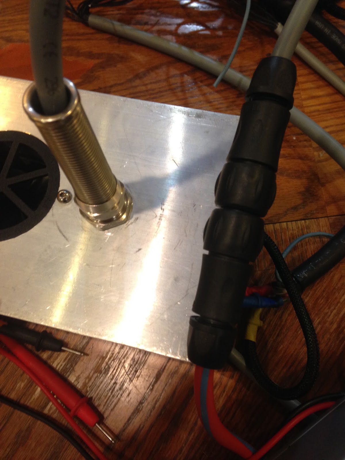
We used a cord grip very similar to the ones found on either end of our watertight compartment, which are described here. The only difference is that there is a short (~3") spring to provide support for the wire entering the cord grip.

Cord Grip w/Support

The cord grip makes sure that the tether is securely attached to the submersible – preventing any slippage – in a way that it both strong and easily removable in case we need to make changes.

Waterproof Connector

The waterproof connector is the one we described in this post. We decided to have a connector outside the submersible so that we could easily detach the sub from the tether, allowing for easier transport and more customizability.

Waterproof Connector

Though we were originally worried about how much force the connector could take, we have found that it holds up very well to the amount of tension it will experience. 

Tether and Connector

8.17.2015

Lighting – Building the LED Mounts

After working on the design for our LEDs we moved onto constructing the mounts. The LED units were fast and easy to cut out once we had access to the Laguna CNC Router we mentioned in this post.

Preparation

We used the same LEDs for these units as we discussed in this post. Just as a refresher, these LEDs are 10W 850nm LEDs. The diodes themselves are 7mmx7mm, but we bought the LED mounted to a 20mm diameter start PCB. This PCB makes it easier for us to mount and heat-sink the LED to our custom LED unit. 
LED ENGIN 850nm on Start PCB (Stock Photo)


To cut out the LED mounts/heat-sinks we used an 1/8" end mill with the Laguna. While cutting the aluminum we had to make sure our feed rate was slow enough so the bit didn't break and that the bit was cooled to ensure clean cutting. For the feed rate we found that 5 inch/minute works the best. We also needed to continually cool the end mill to keep it cutting well. The combination of the feed rate an the WD40 we used for cooling, small bits of a aluminum "sand-castled" around the path of the end mill. Below is a picture of this as well as a short clip of the router cutting our an aluminum heat-sink. 

Cut Aluminum w/ Debris


After cutting out the aluminum we used a hand drill to make two small holes in the back of each of the LED pockets. These holes are used to both route and organize some of our wire.


Back of LED


We then soldered the wires onto the LEDs before mounting them to the aluminum heat-sinks. The first unit we put together we saved the soldering for last. Our heat-sink worked a little too well and made it difficult to heat up the LED enough to solder on the wires. We learned from our mistake though and the second unit we soldered much quicker and cleaner.


Assembly

After preparation we used heat-sink epoxy to attach the back of the start PCBs to the back of the aluminum pockets. After waiting 3 days for the epoxy to fully cure we used a clear epoxy to cover the rest of the PCB and the tops of the wires, which protrude slightly from the pocketed section of our aluminum heat-sink. We made sure to keep the LED lenses clean and to have our epoxy dry flat. Below is an image of the clear epoxy drying over the LEDs. We mounted them in the vice to keep a level surface. If you look close enough you might also be able to see some black – that is where the heat-sink epoxy squeezed up through the star PCB when we epoxied it the first time.


LED Unit Epoxy Drying


After epoxying the LEDs we used a 4M tap to tap the holes in the middle of the unit. We then mounted the units to the front plate of our camera mount (pictured in green at the end of our camera CAD post).

LEDs Mounted to Camera Cover

7.31.2015

Designing RoboGoby's PCBs in Eagle

To make our lives easier we decided to design our own custom PCBs (printed circuit boards) to use in RoboGoby, instead of stripping wires and soldering to prototyping boards. We decided it would be more efficient to design our PCBs in CAD and then have them manufactured for us. Not only does this help remove a lot of clutter inside of the watertight compartment, but it also makes our product look and feel more professional. To design the boards we used Eagle. After designing the boards we used OSH Park for manufacturing.

We started designing the PCBs after we had chosen the sensors and processor for RoboGoby. Due to the number of sensors and controllers we're using in RoboGoby, we needed to make three different boards to accommodate everything while still fitting inside of our aluminum body. The boards are connected via stackable pin headers and ribbon cables. Below are quick descriptions of each board along with a CAD photo.

PCB1 - Micro and LED Control

This PCB houses our LED controllers, main micro controller, and screw terminals. You can see the 4 LED controllers on the left of the board and the place for the micro controller on the right (right above the words RoboGoby). The other pinouts are for attaching stackable headers and screw terminals. The screw terminals will be used to connect our cabling which is routed through our cord grips in our watertight compartment. This type of connection allows us to still be able to remove the wires (by loosening the grips and then just pulling them through) rather than having to solder/unsolder plug connectors in order to pull the wires through the grips.

PCB1 (.brd file)

PCB2 - PWM and Pressure

PCB2 is sits underneath PCB1 and contains our PWM controller and ribbon cable connectors (which connect to PCB3). The 2x3 ribbon cable (upper left of board) is used to transfer power from the electronic speed controller (ESC) battery elimination circuits  (BECs) - routed through PCB3. The 2x5 ribbon cable (bottom left) is used to transfer the signals from one PCB to another. This PCB also has outputs for powering our main processor, the ODROID-XU3 and a sensor mount for our interior pressure sensor. 

PCB2 (.brd file)

PCB3 - ESC PCB

The last PCB we designed is our "ESC PCB". This PCB has a few key functions. It is used to route the PWM input to the motor controllers and also utilize the 5v output from the ESCs onboard BEC. It also houses the current sensors for each of our motors as well as a humidity and temperature sensors. This PCB is not stacked, but sends power and receives data instructions via the two ribbon cables. An image of the Eagle 

PCB3 (.brd file)


Board Layout

In order to layout the pins on our boards and figure out the size requirements we used SolidWords. We made designs for each of the PCBs and holes where each of the sensors were going to go. After laying everything out in SolidWorks transferring the PCB to Eagle was easy – we just had to steal the dimensions from solid works and then route all of our connections. Rough pictures (not 100% accurate – screw terminals were reversed) of the CAD are below:


Stack PCB1 and PCB2


PCB3

The finished boards will be arriving soon so stay tuned for a post about PCB construction!

7.26.2015

Connectors and Cord Grips – Waterproofing our Wiring


One problem with having a waterproof chamber in our submersible is finding a way to get wires in and out without compromising the seal. We have three separate measures that we are taking to make sure that all of our wires are waterproof: we are using five cord grips, a waterproof 3-pin connector, and strategic epoxying.


Cord Grips:

Cord grips allow us to have wires penetrate the waterproof compartment without having to worry about letting water in. We bought submersible cord grips from McMaster (pictured below) and incorporated them into the design of our watertight compartment.

Submersible Cord Grip


As you can see in the picture the back end of the cord grip is threaded which allows us to easily incorporate it into the plugs for our waterproof chamber. Because we are getting the plugs professionally machined we can be confident that they will be tapped correctly, meaning that with the addition of some Blue Loctite the threads will be waterproof to a few hundred feet. Lastly the inside of the cord grip has rubber pieces that tighten around the wires to ensure no water gets past.


Epoxy:

While the cord grips take care of most of the possible entries into the waterproof chamber it leaves one - water that gets inside of the insulation of our wiring and travels through the wire itself and into the chamber. To keep this from happening we will epoxy the endpoints of the wire on both the outside and inside of the waterproof chamber so that even if one is to leak a little the other should keep the water at bay.


Waterproof Connector:

The last piece in our waterproofing system is a waterproof connector. We are using one of these outside of the submersible as a way to easily attach/detach the tether from the submersible. We spent a long time looking for connectors that are actually submersible and not just waterproof as we ran into a few common problems. In a majority of cases connectors are rated as IP67 or IP68, neither of which are submersible (IP68 is submersible but usually only to shallow depths and for limited time, for more look here). When we did find connectors that seemed like they were suitable they were often from large suppliers that only fulfilled orders of hundreds or thousands.

Eventually we found a supplier that has their parts carried by Digi-Key which allowed us to buy individual connectors. The connectors are made by Souriau, this is the catalog we used to order parts. We got a 3-pin connector and 14AWG contacts (which are bought separately from the casing) - specifically we are using the 142G1 series.

142G1 Connector

Instead of having a connector attached to the outside of the body we decided to have a few feet of tether permanently protruding from the submersible. This is because we are not sure how much strain the connectors can take without becoming compromised. Instead the place where the tether enters the submersible is braced with another cord grip as we know that can take a lot of strain.

7.25.2015

Change of Processor – Beaglebone Black to ODRIOD–XU3

About one month ago we decided to change our main processor from the BeagleBone Black to the ODROID-XU3. ODROID stands for Open-Source Android, and is a powerful embedded linux platform. Although the XU3 is more expensive and larger, it is much more powerful than the BeagleBone. In order to run our high-level stereoscopic camera we needed a faster and more powerful computing platform. Some of the specs are below:

      • 2.0GHz Quad-Core CPU
      • 2Gbyte of RAM @ 933MHz
      • eMMC

All of our other computing for our sensors and motor control will be still be done by a smaller micro-controller which we will connect to the ODROID. A stock photo of the ODROI-XU3 is below:


ODROID-XU3


7.13.2015

Lighting – LEDs, PCB Design and Testing

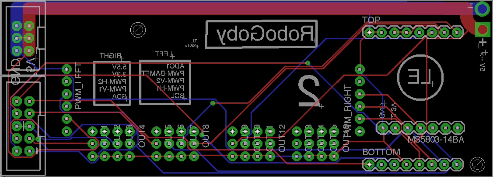
One of the most important parts of our original LED lighting design was size. While we were purchasing small LEDs, they all came pre-sldered to large PCBs (Printed Circuit Boards) to allow for ample surface area for heat-sinking. After choosing to use the these high-power IR LEDs from LED Engin, but they're not available from any distributor until the end of the summer. Because of our time constraint we decided to use the same LEDs, but to purchase the ones already mounted to a PCB and unsolder them. Using the schematics we designed this PCB in Eagle (PCB CAD software):

Eagle Design


After designing the PCB we used OSH Park to fabricate them. The turn around time is about 12 days and the quality is decent. Below is an image of what the top side of the finished PCB looks like:


OSH Park PCB

Because we still wanted to use our custom PCBs and the 12.4V 10 Watt LED Engin LEDs, we needed to unsolder the LED from the manufacters PCB. We used a toaster oven to unsolder the LEDs. Below is our toaster oven:

Toaster Oven


The unsoldering process took longer than expected because of the high temp solder the manufacturers used on the PCB. This meant we had to max out the oven for 5+ minutes to unsolder the lights. Although this was longer than we wanted, we ran with it. After unsoldering the LEDs we then used a Bismuth based solder from Digikey. This stuff is AWESOME and worked extremely well for us. It's perfect for LEDs surface mount soldering because the entire oven never has to get above ~150C – over 100C below the max temperature rating on the LED.

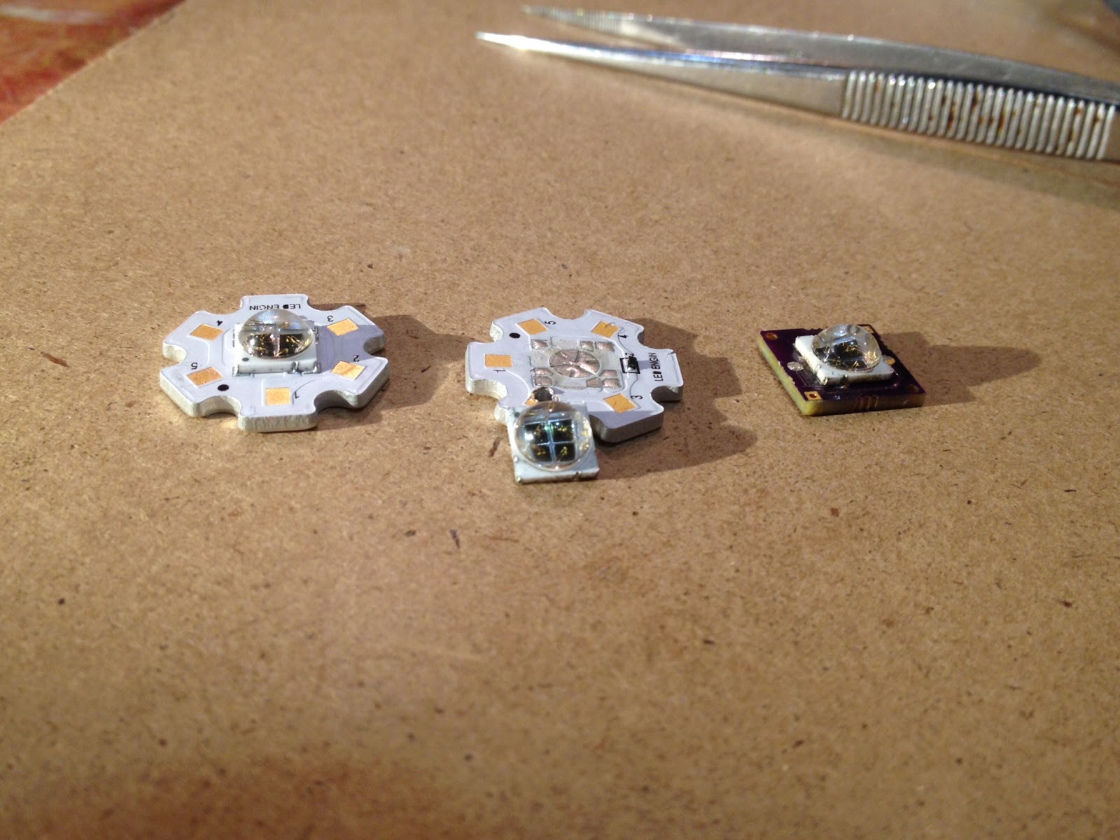
Below is a picture of the different stages of the LED process. On the left is the original LED/PCB combo. In the middle is the LED unsoldered from the PCB. On the right is LED soldered onto our custom PCB.

LED Process
Putting Solder on PCB
LED being Soldered to Custom PCB in Toaster


And here is a close up of the final soldered LED:

LED+PCB


Although the soldering was smooth, the unsoldering process was not. Because of our lack of knowledge we were unable to unsolder an LED without burning out the diodes in the LED (because we had to have the LED in the oven 5+ minutes near it's maximum temp rating). We decided to stick with the original Star PCBs for the sub this summer. It saves us a lot of hassle and money. In the future (when we can buy the LEDs not connected to the star PCB) we will change our lighting design to incorporated this small, more effective PCB.

6.21.2015

Choosing our Sensors

While designing the second version of RoboGoby we needed to decide what sensors were necessary to have incorporated into the basic design. If you have been following our blog you'll remember when we posted this in October 2013. That post had ideas for sensor we had gotten from different research institutions. After spending the past year and a half working on the sub, we created an updated list of sensors we want to have incorporated on the most basic version of RoboGoby. We decide that these environmental sensors are key to a well functioning submersible and are necessary if we want to have a well working product.

The updated list of sensors we chose is below. There is also a short description with each saying why it is important for our design. While choosing the new sensors we also made sure that they all interface with an I2C bus. This allows us to communicate with multiple different sensors while only using a minimal amount of wiring and only a single micro-controller. 

Breakout board w/ MS5803
We chose to use this sensor because it is waterproof and it can withstand up to 14 Bars of pressure, which is around 200 psi or 450 feet underwater. It allows us to determine the depth of the submersible.


We chose to use current sensors on this version of RoboGoby because we wanted the ability to have current control over the thrusters. As are unable to accurately measure the speed of the ROV in all directions, we will be using current to limit the thrust on each of the motors. This will make it easier to implement autonomous capabilities in the submersible. We are using the ADC in order to use multiple analog current sensors without having to use more analog pins. 


This version of RoboGoby has a watertight compartment. Although this design is useful in many ways, we need to make sure that the compartment gets neither wet or too hot.


We chose to use a LIDAR instead of a ultrasonic sensor for ranging underwater. This sensor is very easy to integrate in an underwater environment and has an extremely large range. We will have to calibrate this for the reflectivity of water, but this sensor works for bathymetry, meaning it should also work for our purpose. Its had two advantages over a sonar sensor. The first is that it doesn't have a minimum range (a very small one), which is important if we end up having to navigate without a camera or with limited vision. Second, it is easier to waterproof as we don't have to find a substance which provides waterproofing without having any sound dampening properties. 


This sensor is very similar to the Razor 9DOF IMU we used last year. The only difference between the two sensors is that this one doesn't have a micro-controller built in. Similar to last year, we will be using this sensor to get a better understanding of the submersible's position in the water. This will not only be useful for human drivers, but also useful in implementing autonomous station-keeping and driving.