8.09.2015

Small Thrusters v2.0 – Building

Before reading this you should get acquainted with our design by reading about the CAD models for the small thrusters. As a brief intro, the small thruster is made up of four different parts: the grills, motor mount, thruster curtain, and curtain mount.

Grills

The grills are designed to keep large debris out of the small thrusters. Each thruster has two grills, one on each side of the thruster (to block both ends). We printed all of our grills on a MakerBot Replicator with PLA. The grill sits flat with the exterior of the sub and has 6x.125" spokes to stop material from getting caught in the 2" thruster.

Printed Grill


Motor Mount

The motor mount was cut out of .25" Delrin. Delrin's material properties allow it to be both strong, easy to machine, and, therefore, also nice to tap. Although it is a close cousin on acrylic, is does not shatter or crack as easily.

We went through two different iterations of cuts before we perfected our motor mount. Similar to the grill the motor mount has 6x.125" spokes so they line up with each other.


Motor Mount on CNC
Motor Mount


Thruster Curtain

Version 1

The first version of this years Thruster Curtain was very similar to last years. We cut out 2" PVC pipe and used the lathe function of a Stinger CAMaster CNC router to cut slots in it. These pieces cut out very quickly, but were slightly off due to the imperfections from the lathe.

Lathe attachment on CNC router

Finished PVC Thruster Curtain


Along with the first version of the Thruster Curtain we made a curtain mount. This mount is used to permanently mount one end of the PVC to the aluminum body.This piece was also cut out of Delrin (like the motor mount).

Thruster Curtain Mount (PVC flavor)

Version 2

While the first version of the thruster mount worked well, it was relatively hard to make and imprecise (all due to the lathe function on the CNC router). In Version 2 we decided to 3D print our Thruster Curtains using PLA plastic and a MakerBot Replicator. This was much more precise giving us a better result with less effort!

Printed Thruster Curtain

Assembly

Version 1:

First we used epoxy to glue the Delrin thruster curtain mount to the PVC pipe (thruster curtain). This is a permeant attachment and holes the curtain in place while the sub is running.

Epoxying
Epoxy drying

Although epoxying the curtains together worked well, we decided to use the printed curtains instead.


Version 2:

Assembling the printed curtains for the through hole thruster was easy. We just needed to add M4 threaded inserts to the printed plastic to allow us to mount the curtain using bolts. To do this, we heated them up with a heat gun, pressed them into the plastic, and then mounted them in place. This allowed them to cool and set in the correct orientation.

Threaded Insert


We then mounted our finished motors to the Delrin motor mounts.


Motor in Mount

One Mounted Motor

Five Mounted Motors


Note:
While it is hard to see in these pictures we wanted to make sure that the bolts didn't protrude from the mounts, so we got M3 bolts that have beveled heads, allowing us to sink them into the delrin mounts.

And here the mounted motor is fit inside of the thruster curtain:


Motor in Curtain

Motor in Curtain Size Reference


To finished mounting the thruster we pressed the grills into the holes in our aluminum body and slid the thruster curtain/mounted motor combination into place. We then used six M4 bolts (three on each side) to mount the thruster in place.

Two Mounted Thrusters

8.08.2015

Preparing Thrusters – NTM Prop Drive and Aerodrive SK3 Shaft Extension & Reversal

Before building our complete thruster units we needed to prepare the motors we purchased in order for them to work in our design. We used the NTM Prop Drive series for our small thrusters (vertical and horizontal) and we used the Turnigy SK3 for our large rear thruster.

NTM Prop Drive – 750KV

NTM Prop Drive (stock photo from HobbyKing)


Turnigy Aerodrive SK3 – 350KV

Turnigy Aerodrive (stock photo from HobbyKing)

The motors above are Outrunners, a type of brushless motor. These motors offer us more torque because, unlike the familiar brushed motors, the magnets on outrunner motors are located outside of the copper coils rather than on the inside. This characteristic is extremely useful when you need a lightweight motor to produce a lot of torque.

NTM Prop Drive – Preparing for  the Through-Hole Thrusters

Before assembling our thrusters we needed to prepare them. This meant we had to mount our propellors and shafts to the motors before attaching them to the motor mounting plate. Although this is fairly straight forward, we had to fiddle with the motors in order to get them in our final configuration.

Our first idea for attaching the shaft extension was by press fit. We were going to reverse the motor shafts and then then press our shaft extensions onto them. We did this last year and it worked well. Our second idea for mounting the propellor was purchasing a CNCed propellor adapter, something we did not try last year.

Press Fit Setup – NTM Prop Drive Shaft Reversal

Before we could attach the shaft extensions or add on the threaded shaft attachment to the motor, we had to reverse the motor direction. This would allow us to use the side of the motor that has four holes for mounting while having the shaft stick out in the other direction. The process is pretty simple with a brushless motor.

The first step is taking the motor apart. To do this remove the c-clip (shown below) from the shaft and then the set screw (holds the shaft to the exterior of the motor) from the motor cover. At this point the motor should come apart into three pieces, though the shaft may take a few taps with a hammer to hit it loose.
C-Clip

Once the motor is in three parts – a shaft, a motor cover (w/ field magnets), and the armature (copper coils) – simply spin the shaft 180° and put the cover back over the armature. Instead of using a c-clip in the reversed set-up a shaft collar (pictured below) is needed. In the pack of shaft collars that we got the set screws were so long (5mm) that they stuck out and hit our motor mount. The fix was simple: we bought new 3mm long set screws. The shorter set screws sit below the circumference of the circle and so allows for the collar to act as a bearing inside of our motor mount. Finish by replacing the set screw that was originally in the motor cover to re-attached the shaft to the motor cover. You now have a forward facing shaft.

Shaft Collar (stock photo)

Top to Bottom:
Before, During, and After Reversal

Propellor Adapter Setup

To mount this the threaded mounting plate to the NTM, you'll have to purchase the NTM Prop Drive Accessory Kit. You will only need the propellor adapter from this kit (image below).


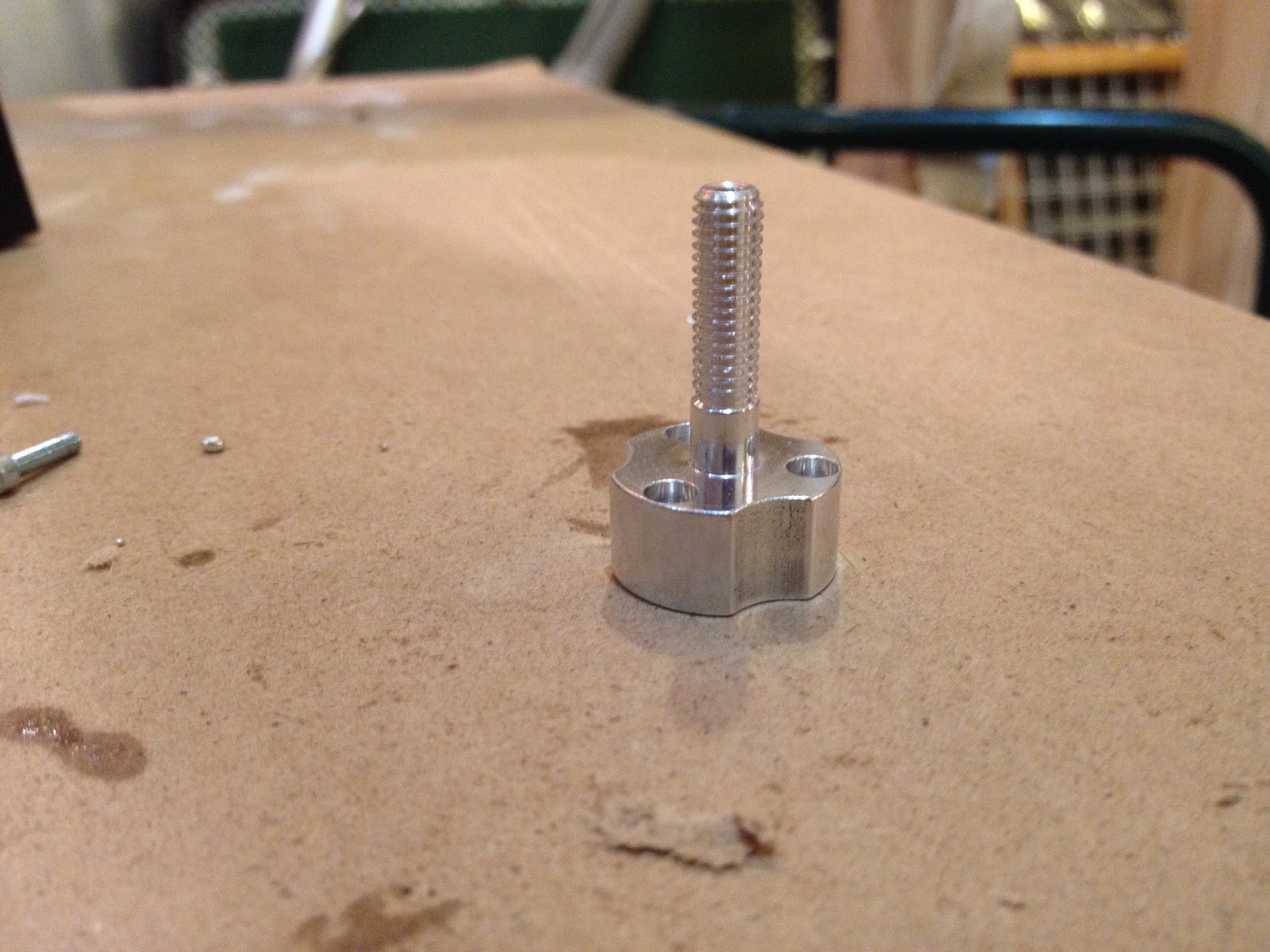
Propellor Adapter

Next, instead of reversing the shaft, you'll want to remove it and then cut it so it sits flat with the back (non-rotating part) of the motor. You then screw on the propellor adapter and... voila! You now have a forward facing shaft!


Propdrive w/ Prop Adapter


After some discussion we decided on using this second method to mount our shaft extensions. This seemed better mainly because we did not need to make a permanent, press-fit attachment to our motors. The propellor adapter gives us the freedom to remove the shaft extensions whenever we please.

Shafts

The propellor extensions for the NTM Prop Drive were designed with 10mm rod, threaded for M4 on one end and M5 on the other. These parts were machined at Porter's Precision Machining in Lewiston, Maine. The M4 end is for attaching the propellor while the 5M end is for the propellor adapter. A CAD image and finished image of our motor, shaft extension, and propellor combination are both below:


Small Motor w/ Shaft Extension&Prop


Prepared NTM 750kv


Turnigy Aerodrive SK3 – Preparing the Large Thruster

To prepare this motor we also decided to use a propellor adapter (image above), a part that comes with this motor when you purchase it from HobbyKing. This propellor adapter is almost identical to the one used on the NTM series (above). 

Prop Adapter on SK3

The shaft extension we designed for this motor was slightly more complicated because of the design of the propellor we're using. Unlike the threaded props we used for the small through-hole thrusters, the large prop for the rear thruster does not come threaded. This meant we had to account for the torque on the prop by adding slots to lock it in place. One end of this shaft is threaded to lock onto the propellor adapter while the other is threaded to fit a lock nut used to hold on the large propellor.


Prop on Shaft Extension
Shaft Extension


And below is a CAD drawing along with a picture of the prepared Aerodrive SK3:

Large Motor w/ Shaft Extension&Prop


Prepared SK3


We also thought a comparison picture of the large thruster and the small vertical/horizontal thrusters would be helpful:


Thruster Comparison

8.06.2015

Inside the Watertight Compartment – Design

After designing the watertight compartment we started working on laying-out its internals. This section of the submersible is the brain of the robot – it houses the computers, sensors, and power electronics that give RoboGoby life.

This section has two parts: the electronics plate and the rails. The electronics plate houses all of our electronics (custom PCBs, ESCs (electronic speed controllers), ODROID-XU3) to make accessing everything easier. The rails act as a guide for the electronics plate as well as help hold in our power supply and Ethernet over Power (EoP) unit.

We are planning on using small neodymium magnets to connect the electronics plate to the rails and to hold the rails together. This makes it easy for us to put the interior of the compartment together without having to unbolt anything or epoxy anything to the aluminum frame. All of the shallow, small holes in the pictures below are for small magnets.

Electronics Plate

Our electronics plate is extremely simple – it's a piece of Delrin plastic with holes for mounting all of our electronics. The plate is 12 inches long with the ESCs mounted down one side of the plate and custom PCBs on the other. The ODROID takes up an entire end of the plate. The Delrin plate also has holes for mounting the magnets mentioned in the introduction. 


Electronics Plate
Magnet Mounts:

Because the electronics plate is going to be very thin (~1/16"), we were not going to be able to mount the magnets directly into the sheet of Delrin. Our solution was to 3D print some small mounts for the magnets. The front of the mount has a pocket for the magnet and the back has a protrusion to fit into the electronics sheet.

Magnet Mount Front

Magnet Mount Side

Rails

There are two rails (one on each side) that are each made up of a large and small part.

Large:

The large pieces are the part of the rails we will not be removing. We'll hot glue these into place at the back of the compartment. The large pieces will act as rails for our electronics plate while also holding our power supply in place. You can see the upside down 'L' in the picture below – this shape perfectly fits the form of our power supply and help holds it in place.


Large Rail


Small:

This is the removable part of our rails. It's added after putting in our power supply and is used to secure the power supple between the two rails. Again you can see the upside down "L". This "L"  is designed to hold the power supply snug against the Large Railing's "L". The small rails attach via magnets to the large stationary rails.


Small Rail


EoP Mount:

The last component that's part of our rail system is the EoP mount. This mount is another removable parts that magnetizes to part of one of the Small rails. It's used to hold the EoP in place within the compartment.


Entire Interior:

This picture shows the electronics plate, rails, and power electronics in their organized states. The large gray box on the bottom is the power supply, which sits next to the EoP in its mount. Above those, on the railings, is the elctronics plate.

Assembled Mid-section

7.31.2015

Designing RoboGoby's PCBs in Eagle

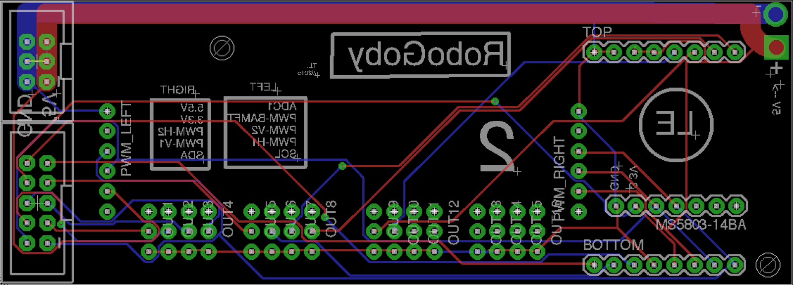
To make our lives easier we decided to design our own custom PCBs (printed circuit boards) to use in RoboGoby, instead of stripping wires and soldering to prototyping boards. We decided it would be more efficient to design our PCBs in CAD and then have them manufactured for us. Not only does this help remove a lot of clutter inside of the watertight compartment, but it also makes our product look and feel more professional. To design the boards we used Eagle. After designing the boards we used OSH Park for manufacturing.

We started designing the PCBs after we had chosen the sensors and processor for RoboGoby. Due to the number of sensors and controllers we're using in RoboGoby, we needed to make three different boards to accommodate everything while still fitting inside of our aluminum body. The boards are connected via stackable pin headers and ribbon cables. Below are quick descriptions of each board along with a CAD photo.

PCB1 - Micro and LED Control

This PCB houses our LED controllers, main micro controller, and screw terminals. You can see the 4 LED controllers on the left of the board and the place for the micro controller on the right (right above the words RoboGoby). The other pinouts are for attaching stackable headers and screw terminals. The screw terminals will be used to connect our cabling which is routed through our cord grips in our watertight compartment. This type of connection allows us to still be able to remove the wires (by loosening the grips and then just pulling them through) rather than having to solder/unsolder plug connectors in order to pull the wires through the grips.

PCB1 (.brd file)

PCB2 - PWM and Pressure

PCB2 is sits underneath PCB1 and contains our PWM controller and ribbon cable connectors (which connect to PCB3). The 2x3 ribbon cable (upper left of board) is used to transfer power from the electronic speed controller (ESC) battery elimination circuits  (BECs) - routed through PCB3. The 2x5 ribbon cable (bottom left) is used to transfer the signals from one PCB to another. This PCB also has outputs for powering our main processor, the ODROID-XU3 and a sensor mount for our interior pressure sensor. 

PCB2 (.brd file)

PCB3 - ESC PCB

The last PCB we designed is our "ESC PCB". This PCB has a few key functions. It is used to route the PWM input to the motor controllers and also utilize the 5v output from the ESCs onboard BEC. It also houses the current sensors for each of our motors as well as a humidity and temperature sensors. This PCB is not stacked, but sends power and receives data instructions via the two ribbon cables. An image of the Eagle 

PCB3 (.brd file)


Board Layout

In order to layout the pins on our boards and figure out the size requirements we used SolidWords. We made designs for each of the PCBs and holes where each of the sensors were going to go. After laying everything out in SolidWorks transferring the PCB to Eagle was easy – we just had to steal the dimensions from solid works and then route all of our connections. Rough pictures (not 100% accurate – screw terminals were reversed) of the CAD are below:


Stack PCB1 and PCB2


PCB3

The finished boards will be arriving soon so stay tuned for a post about PCB construction!

7.27.2015

Watertight Compartment – CAD Model

One of the most integral pieces to our new sub design is a watertight compartment. In our previous design, RoboGoby Version 1.0, we decided to avoid the difficulties of making our own watertight compartment by potting all of our electronics in epoxy. While at the time this seemed like a good idea it ended up being a big problem for us. After epoxying our electronics we couldn't access anything which meant it was harder to debug our system and to add to our platform. Based on this experience we decided to make our lives easier this year (and in the long run) by designing our own watertight compartment. The two key pieces to our compartment are the machined aluminum pieces and the watertight connectors.

Machined Parts

At first we struggled with the type of seal we were going to use for the compartment. Although we knew we wanted to use an o-ring seal, we wanted something that would give us the largest opening into the watertight compartment and keep it within the 5"x5" size of our sub. Our first thought was to use an axial o-ring seal. While this seal is effective, it takes up too much room for a number of reasons. First off this type of seal needs constant pressure around its circumference which means we would have need 8+ bolts to create a good seal. Secondly, we want to use a double seal to ensure our compartment doesn't leak – with two axial o-rings the access opening would go under 3.5", which is too small to be useful. While talking with one of our mentors, Jon Amory, he mentioned the idea of using a radial o-ring seal. This design would follow the form of our sub better (it is longer not wider) and therefore would allow us to have both a larger access hole and a double seal while still fitting inside of our 5"x5" constraint.


Radial Seal (Apple Rubber)
Axial Seal (Apple Rubber)


To design the aluminum fittings we used Apple Rubber, an rubber engineering company. They have a great introduction to o-ring design (static o-ring seal descriptions found here).

On one end of the compartment, the access end, we designed a plug and a plug housing. The plug is made out of a 4.75"x4.75"x2.5" piece of aluminum. The plug itself acts like a cork to keep the air in and water out of our compartment. The inside of the plug is hollowed out and has holes for running wires through. One side is square to match the interior of our sub body. An image of the plug is below. If you look close enough you'll also see a radial hole in the pocket -- this is for a bolt we will use to pull out the plug, a necessary feature because it will take a large amount of force.


Plug
The plug housing is a also a 4.75"x4.75"x2.5" aluminum block with a pocket  diameter of 4" cut all the way through the material. It also has four mounting holes on one of the faces to accept the 6mm bolts that hold the plug in place. There are also four bolts on the exterior (two on each side) which are used to hold the sections together. An image of the plug housing is below:

Plug Housing

And  the two fitting together (with a transparent plug housing):


Assembled Seal

The third, and final, piece is the back plug. This part covers the end of the watertight compartment that will never be opened. It is made out of a 4.75"x4.75"x2.5" piece of aluminum. It has a large square pocket 2.25" deep and 3.25"x3.75". The plug housing has such a large pocket to give us more room inside of the watertight compartment for our electronics. Similar to the plug housing, the back end of the compartment has four bolt holes (two on each side) to connect sections together. Below is a picture of the part:

Back End

We will be welding the parts to our 5"x5" sub body to finish the watertight compartment. The aluminum parts slide into the compartment about .5", more than enough room to hold it in place while being welded from the outside. A picture of the finished compartment is below:

Watertight Compartment


Watertight Connectors

As you probably noticed, the pieces talked about above have holes through them. These will in fact be used for routing the wires inside of RoboGoby. The five larger holes on the back end plug and the plug itself are holes for cord grips which will keep our electronics sealed off (read more here). The 6th and final hole, which can be found on the plug, is a threaded hole for a Presta valve. We are going to use the valve to pressurize the compartment to relieve strain on the o-rings and quickly alert us of any leaks in our housing (when combined with a pressure sensor).

Plug Assembly w/ Connectors

7.26.2015

Connectors and Cord Grips – Waterproofing our Wiring


One problem with having a waterproof chamber in our submersible is finding a way to get wires in and out without compromising the seal. We have three separate measures that we are taking to make sure that all of our wires are waterproof: we are using five cord grips, a waterproof 3-pin connector, and strategic epoxying.


Cord Grips:

Cord grips allow us to have wires penetrate the waterproof compartment without having to worry about letting water in. We bought submersible cord grips from McMaster (pictured below) and incorporated them into the design of our watertight compartment.

Submersible Cord Grip


As you can see in the picture the back end of the cord grip is threaded which allows us to easily incorporate it into the plugs for our waterproof chamber. Because we are getting the plugs professionally machined we can be confident that they will be tapped correctly, meaning that with the addition of some Blue Loctite the threads will be waterproof to a few hundred feet. Lastly the inside of the cord grip has rubber pieces that tighten around the wires to ensure no water gets past.


Epoxy:

While the cord grips take care of most of the possible entries into the waterproof chamber it leaves one - water that gets inside of the insulation of our wiring and travels through the wire itself and into the chamber. To keep this from happening we will epoxy the endpoints of the wire on both the outside and inside of the waterproof chamber so that even if one is to leak a little the other should keep the water at bay.


Waterproof Connector:

The last piece in our waterproofing system is a waterproof connector. We are using one of these outside of the submersible as a way to easily attach/detach the tether from the submersible. We spent a long time looking for connectors that are actually submersible and not just waterproof as we ran into a few common problems. In a majority of cases connectors are rated as IP67 or IP68, neither of which are submersible (IP68 is submersible but usually only to shallow depths and for limited time, for more look here). When we did find connectors that seemed like they were suitable they were often from large suppliers that only fulfilled orders of hundreds or thousands.

Eventually we found a supplier that has their parts carried by Digi-Key which allowed us to buy individual connectors. The connectors are made by Souriau, this is the catalog we used to order parts. We got a 3-pin connector and 14AWG contacts (which are bought separately from the casing) - specifically we are using the 142G1 series.

142G1 Connector

Instead of having a connector attached to the outside of the body we decided to have a few feet of tether permanently protruding from the submersible. This is because we are not sure how much strain the connectors can take without becoming compromised. Instead the place where the tether enters the submersible is braced with another cord grip as we know that can take a lot of strain.

7.25.2015

Change of Processor – Beaglebone Black to ODRIOD–XU3

About one month ago we decided to change our main processor from the BeagleBone Black to the ODROID-XU3. ODROID stands for Open-Source Android, and is a powerful embedded linux platform. Although the XU3 is more expensive and larger, it is much more powerful than the BeagleBone. In order to run our high-level stereoscopic camera we needed a faster and more powerful computing platform. Some of the specs are below:

      • 2.0GHz Quad-Core CPU
      • 2Gbyte of RAM @ 933MHz
      • eMMC

All of our other computing for our sensors and motor control will be still be done by a smaller micro-controller which we will connect to the ODROID. A stock photo of the ODROI-XU3 is below:


ODROID-XU3


7.20.2015

Compiling a Linux Kernel for DUO3D Arm Module/Driver

As part of their developer program ($95 per year @ https://duo3d.com/program/developers), Code Laboratories provides a kernel level driver source for their DUO cameras that can be compiled on an embedded Linux kernel. This compilation produces a .ko file that can be inserted into the kernel (the level of the operating system that handles communication between the user and the user interface and the actual physical components of the system, such as the DUO camera and USB drives) to drive the camera on almost any embedded Linux device (although only some are powerful enough to run the camera). Here, we will go over the general method of compiling these DUO drivers, although I will be using the Odroid XU3, one of the boards that Code Laboratories recommends. It is important to note that, in our experience, boards like the Beaglebone and the Raspberry Pi, while useful in their own right, are not powerful enough to run a DUO camera in any useful capacity. We recommend using the Odroid XU3 as it is the smallest of Code Laboratory's recommended boards or another of their recommended boards, like the Nvidia Jetson.

After applying for Code Laboratory's developer program, you should be able to download a from your account page a special package of DUO software for arm under the section DUO Developers. Store this in your user profile folder (/home/[user] or simply ~) on your Linux device. Inside the folder should be a readme file with specific instructions on how to compile the driver for the Nvidia Jetson. These instructions are pretty close to universal, but not quite.

The next step is to get the latest kernel source for your device. Many companies, like Odroid, distribute custom kernel sources for each of their devices (the Odroid XU3 Linux Ubuntu source can be found here: https://github.com/hardkernel/linux/tree/odroidxu3-3.10.y and can be downloaded using the command:


git clone --depth 1 https://github.com/hardkernel/linux.git -b odroidxu3-3.10.y

in the directory in which you want to download it [we recommend ~ also]). The latest Linux kernels can be found here 


Make sure you get one that is right for your device. This may require using google on your part, but any documentation for your device should include a location for the kernel source. Once you have the source, take a look at the readme provided by Code Laboratories (CL). you can largely ignore the prerequisites as most systems embedded have GCC compilers and debuggers. You also don't need QT, Cmake or opencv unless you are planning on compiling CL's examples. Start by following their example and cd-ing into your kernel source directory, which, if you used the command above to get your kernel, would be 

 cd odroidxu3-3.10.y

You now have to configure your kernel. The kernel has thousands of configuration files for different systems. For the Odorid XU3, you can use make odroidxu3_defconfig to configure the kernel. Otherwise, you can look for a similar command for your own kernel online or use make menuconfig or make oldconfig to configure manually. 

Next, follow steps two and three as laid out by CL's readme. You don't have to use gedit to edit the file you are patching but can replace it with "nano," a more common but less robust utility, and then use ctrl + W to search for the lines they want you to comment out.

Now you're ready to make your kernel. Enter these commands in succession, waiting for each to finish (which may take a while) before entering the next. NOTE: the -j switch specifies the number of cores you wish to use while compiling the kernel. The number you pass it is 1 + the number of cores you want to use. The Odroid XU3 has 8 cores, so use 9 for the maximum compilation power.

make zImage -j9 

make modules

make modules_install

Before you do anything else, check the output of the command uname -r and record it. This is your current kernel version and you will want to check if it has updated. Now follow the last command in step 5 of the CL instructions to copy the newly generated zImage from the kernel source to your devices boot directory. Before you do this, you may want to do some searching to make sure that this is where you need to move your zImage (it sometimes depends on the device or on the version of the kernel). 

Now restart your device and again execute the command uname -r to check if your kernel version now matches that of the one you downloaded and patched. If it does not, you may have put the zImage in the wrong directory. 

Next, cd into the DUODrivers directory in the file you downloaded from CL. There are three files of interest: InstallDriver, LoadDriver, and UnloadDriver. Run the command: chmod +x targeting all three of these files, then ./ the first two to load your driver and ensure that it loads whenever you start your device. To check if it has loaded, verify the duo0 node is in the /dev diectory and run the command  lsmod to list active modules. Look for the duo module there. If this all checks out, you should be all set.

Finally, make sure you copy the libDUO.so library into the /usr/lib directory as the linker needs to know where this library is at run-time.

And that's it! The kernel is now compiled.