7.16.2015

Lighting – CAD Model

The lights in our newly designed submersible will hopefully look much nicer than previously. Our previous lighting solution was a little ugly and didn't work well in practice. The problem we had faced was fitting the LEDs, three cameras, and all the mounts inside of a 4" diameter PVC pipe. The switch to a 5" cuboid makes mounting the lights much easier. It not only gives us much more room, but also makes for an easier mounting surface.

Below are the three major iterations that the new sub's lighting design went through. The last design is the one we decided to use.

Version 2.1

Our first idea was to mount the lights on strips across the top and bottom using acrylic and aluminum.

LED Slabs

The problems with this idea were numerous. It limited the space for the camera and greatly diminished the angle of illumination from the LEDs. It also increased the coefficient of drag when moving forward because flat plates are much worse than either domes or cylinders. Having three lights in one packages also made each of the light slabs $100 which would make replacement costly. The only pro was the ease of production. After weighing the pros and cons we felt there was enough reason to revamp the design.

Version 2.2

After discussing a few other ideas we settled on this design. This design (pictured below) incorporates the LEDs and heat-sinks into the form factor of the sub. This gives us all of the function of the previous design, while illuminating much more space.

LED Heat-sinks w/ LEDs

We decided on grouping the LEDs across from one another. We have one set of lights centered, two sets aimed downwards, and one set aimed upwards. The decision on the placement of the LEDs stemmed from three places. The first is that we wanted to have at least one set looking almost directly forward to ensure enough light for navigation. The second was that we wanted to save some money and have 8 and not 10 total LEDs. Thirdly, due to the last two constraints, we decided to have two sets facing down and only one facing up because we expect users to spend more time looking down at the sea floor rather than the surface of the water.

We then had to create a case for the LEDs. Our first idea was to mount them directly to the heatsink with epoxy so that they would be completely waterproof. Unfortunately this solution is not very good for replacing burnt out LEDs, as we would have to replace both good and bad LEDs as well as the entire heat-sink.

Our solution was to make a separate case for each LED. The first case design had four sides closed by a 3D printed piece of plastic. The fith side we left open and the  sixth side will be made from a 1/16" piece of aluminum to give us a larger area of contact between the LED and the curved heat-sinks. An important aspect to this design was a 12mmx12mm PCB for our high power LEDs. This small PCB allowed us to make the cases small, but we still ran into problems. If you'd like to read more about our small PCB adventure read this post.

We went through a few different version of the small 3D printed case. Below is the old design we used to test the printer accuracy with:

Old 3D Printed Case (4 sides)
Entire LED Module (old)


We then moved onto the real print, only changing few parts of the case. The changes we made were closing the 5th edge of the case and curving the mounting edge to better fit the form factor of the aluminum heat-sink. The light, however, fits the same into the case.


Updated LED Case

Although this design is effective, it is costly and time consuming. We have to buy 8 LEDs are re-solder them onto the correct size PCB.  The aluminum is also expensive and time consuming to make. Therefore we decided to work on a third and final light design. 


Version 2.3

Our third design uses only 4 LEDs and takes advantage of the rotation of the camera by mounting to the same servo as the camera. We originally decided to stay away from this type of light setup because of the reflection back into the camera, but when using bent polycarbonate the light is not reflected back into the camera (this has been tested empirically). We also kept the LEDs on the star PCBs they come on, sinking them into a piece of aluminum (in the future we will buy the individual LEDs, but as we said in this post, it wasn't an option this summer). Below is an image of an LED module. 


LED Array

We then mounted the array above on either side of the camera using 3M bolts (refer to this post for color scheme).


Lights Straddling Cam


This is the design we finally settled on. Not only does it provide ample light for our camera, but it allows us to minimize the size and cost of our system. By allowing the lights to rotate with the camera we keep our illumination at a maximum while keeping our design simple. Stay tuned to find out how the building of this section goes! 

7.13.2015

Lighting – LEDs, PCB Design and Testing

One of the most important parts of our original LED lighting design was size. While we were purchasing small LEDs, they all came pre-sldered to large PCBs (Printed Circuit Boards) to allow for ample surface area for heat-sinking. After choosing to use the these high-power IR LEDs from LED Engin, but they're not available from any distributor until the end of the summer. Because of our time constraint we decided to use the same LEDs, but to purchase the ones already mounted to a PCB and unsolder them. Using the schematics we designed this PCB in Eagle (PCB CAD software):

Eagle Design


After designing the PCB we used OSH Park to fabricate them. The turn around time is about 12 days and the quality is decent. Below is an image of what the top side of the finished PCB looks like:


OSH Park PCB

Because we still wanted to use our custom PCBs and the 12.4V 10 Watt LED Engin LEDs, we needed to unsolder the LED from the manufacters PCB. We used a toaster oven to unsolder the LEDs. Below is our toaster oven:

Toaster Oven


The unsoldering process took longer than expected because of the high temp solder the manufacturers used on the PCB. This meant we had to max out the oven for 5+ minutes to unsolder the lights. Although this was longer than we wanted, we ran with it. After unsoldering the LEDs we then used a Bismuth based solder from Digikey. This stuff is AWESOME and worked extremely well for us. It's perfect for LEDs surface mount soldering because the entire oven never has to get above ~150C – over 100C below the max temperature rating on the LED.

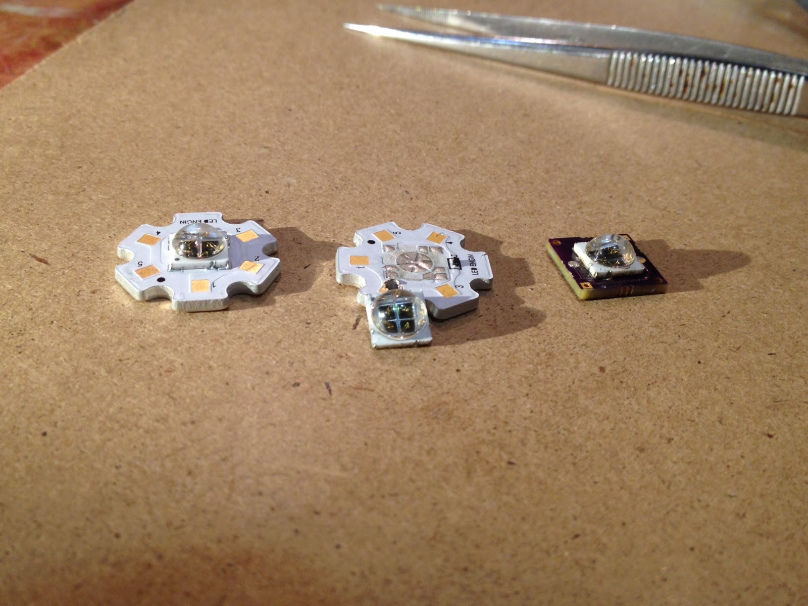
Below is a picture of the different stages of the LED process. On the left is the original LED/PCB combo. In the middle is the LED unsoldered from the PCB. On the right is LED soldered onto our custom PCB.

LED Process
Putting Solder on PCB
LED being Soldered to Custom PCB in Toaster


And here is a close up of the final soldered LED:

LED+PCB


Although the soldering was smooth, the unsoldering process was not. Because of our lack of knowledge we were unable to unsolder an LED without burning out the diodes in the LED (because we had to have the LED in the oven 5+ minutes near it's maximum temp rating). We decided to stick with the original Star PCBs for the sub this summer. It saves us a lot of hassle and money. In the future (when we can buy the LEDs not connected to the star PCB) we will change our lighting design to incorporated this small, more effective PCB.

7.05.2015

Camera & Front Sensor Mounts

Camera Mount:

The camera mount is made of four distinct pieces. There are two parts that hold the camera system in place, the servomotor motor mount and the bearing mount. The other two parts are the shaft and camera mount.

Below are the two side mounts. One side holds the servo motor and the other side acts as a bearing for the shaft which the camera is mounted to.

Servomotor Mount
Shaft Bearing Mount


We thought about putting a bushing in the hole instead of using the plastic support as a bearing, but we decided against it as the printer plastic is quite slick.


The third part is the shaft on which the camera rotates. The white piece on the end which attaches to the servo motor is a servo horn that comes packaged with the servo motor. The shaft has a large mount connected to it. This makes a "shaft extension" that has three main functions. First, it has holes which attach it to the white piece on the servo, holding the piece to the shaft. Second, the two holes on the bottom are to hold the camera case to the shaft. Third the four top holes and two half circles are a LIDAR mount (see below).

Shaft Side View

Shaft Isometric View

The final part of the camera mount is the camera case itself. The case will be filled with epoxy, which is why there is a front as it makes it easier to keep epoxy off of the lens. The hole in the top is for the USB cable, which we are using to communicate with the camera board. 

Camera Case


Integrated LIDAR Mount

Our front facing LIDAR is attached to the camera system so that they tilt in conjunction with each other. As mentioned above the mount is part of the camera shaft mount. It consists of four bolt holes to attach the sensor and two arcs for the circular "lenses" to rest on. 

LIDAR in Mount


Entire Camera & LIDAR Mount


--------------------------------------------------------------------------------------------------------------------------

UPDATE (7/13/2015): A New Camera Mount

After finalizing the design for out lighting system we needed to change a few things on the camera mount (but kept the sensor mount). Using the same basic idea we consolidated the pieces from the previous mount and cleaned things up a bit.

We kept the same basic design for the shaft mount as above, but added a camera case to it. While this definitely stressed the 3D printer to its maximum ability, we thought it was important for a simpler design. This piece is mounted to a rotating shaft (controlled by a servo) and then mounts to the front facing LiDAR, the stereoscopic camera, and the IR LEDs. It can be considered one of the most important parts of the sub design. An image of the mount is below:

Camera + LiDAR + LED Mount

The face piece to this design is also very important because it holds LED mounts. This piece is made out of Delrin for extra stability. The large holes in the plastic are for the cameras, the medium sizes holes are for 3mm bolts, and the small holes are for 2mm bolts. 

Cam Cover and LED Mount


We also changed the Servo Mount and the Shaft Bearing Mount. These new mounts were incorporated into the half-circular mounts that replaced the LED heat-sinks (changed with lighting design change). The updated mounts are pictured below. The one on the right is the servo mount as well as the right hand cover. The left has the shaft bushing and acts as the left side cover.


Then using these mounts and putting everything together we get the final assembly for the front of the sub:


Front Mounts&Sensors


As you can see this design not only has less pieces than the other design, but it looks much better overall.

--------------------------------------------------------------------------------------------------------------------------


Front Sensor Package

Just behind the camera and in front of the foremost thruster we put a pack of sensors. The pack consists of a depth sensor, an IMU and a downward facing LIDAR. The IMU is on the central axis of the sub and the depth sensor is just in front of it - there is also a track we will use to route wires. The hole and bolts for the LIDAR are on the left side of the sub (right side of the image). The LIDAR sticks out the bottom of the mount so that it is flush with the bottom of the submersible body.


Front Sensor Package

And this is a picture of both the camera mount and the sensor package mounted in the front of RoboGoby:

Camera and Sensor Mount


6.21.2015

Choosing our Sensors

While designing the second version of RoboGoby we needed to decide what sensors were necessary to have incorporated into the basic design. If you have been following our blog you'll remember when we posted this in October 2013. That post had ideas for sensor we had gotten from different research institutions. After spending the past year and a half working on the sub, we created an updated list of sensors we want to have incorporated on the most basic version of RoboGoby. We decide that these environmental sensors are key to a well functioning submersible and are necessary if we want to have a well working product.

The updated list of sensors we chose is below. There is also a short description with each saying why it is important for our design. While choosing the new sensors we also made sure that they all interface with an I2C bus. This allows us to communicate with multiple different sensors while only using a minimal amount of wiring and only a single micro-controller. 

Breakout board w/ MS5803
We chose to use this sensor because it is waterproof and it can withstand up to 14 Bars of pressure, which is around 200 psi or 450 feet underwater. It allows us to determine the depth of the submersible.


We chose to use current sensors on this version of RoboGoby because we wanted the ability to have current control over the thrusters. As are unable to accurately measure the speed of the ROV in all directions, we will be using current to limit the thrust on each of the motors. This will make it easier to implement autonomous capabilities in the submersible. We are using the ADC in order to use multiple analog current sensors without having to use more analog pins. 


This version of RoboGoby has a watertight compartment. Although this design is useful in many ways, we need to make sure that the compartment gets neither wet or too hot.


We chose to use a LIDAR instead of a ultrasonic sensor for ranging underwater. This sensor is very easy to integrate in an underwater environment and has an extremely large range. We will have to calibrate this for the reflectivity of water, but this sensor works for bathymetry, meaning it should also work for our purpose. Its had two advantages over a sonar sensor. The first is that it doesn't have a minimum range (a very small one), which is important if we end up having to navigate without a camera or with limited vision. Second, it is easier to waterproof as we don't have to find a substance which provides waterproofing without having any sound dampening properties. 


This sensor is very similar to the Razor 9DOF IMU we used last year. The only difference between the two sensors is that this one doesn't have a micro-controller built in. Similar to last year, we will be using this sensor to get a better understanding of the submersible's position in the water. This will not only be useful for human drivers, but also useful in implementing autonomous station-keeping and driving. 

6.20.2015

Choosing a Camera – Update

The search for a camera to use in our robot has been long and involved. Throughout the process, we have worked toward finding a camera that satisfied a basic set of requirements. Our camera needs to be capable of outputting high quality video, interfacing with C++ or Java through the Beaglebone black, and be capable of stereoscopic imaging. We believe we have finally found a camera that can satisfy all of those requirements: the DUO MLX.
This camera, while expensive, boasts an impressive array of features and capabilities. It stereoscopic and infrared, allowing it to judge depth in low light environments. It comes equipped with a small array of programmable infrared LEDs and an on-board 9-DOF freedom IMU, allowing it to sense its orientation with a high degree of accuracy. Finally, it comes with a SDK which, just recently, allows it to interface with ARM based micro-controllers like the Beaglebone - although access to this capability requires subscription to DUO's developer program. This SDK is compatible with C++ and C, as well as Java through the Java Native Interface. Another distinct advantage of this camera is its form factor. It is very small, being only 52mm long. This will allow us to fit many more design features into the front portion of the submersible.

6.17.2015

Small Thrusters v2.0 – CAD Model

We recently finished the final CAD model for the small thrusters we're using in our submersible. Four of these thrusters, two vertical and two horizontal, helps our submersible attain 4 of our submersibles 5 degrees of freedom.

The design of the small thrusters was focused around designs that were both easy to build and easy to install. We decided to work off of last years design, keeping the same idea, but tweaking it to fit in the new form factor of the sub. Each thruster assembly has only 5 total parts (excluding the motor and prop) making it an easy part to build and assemble. An image of the finished thruster is below:


Thruster Assembly


This design consists of four main parts: the thruster grill, motor mount, PVC mount, and the PVC piping. In the image above the PVC is transparent, the grills are black and both the motor and PVC mounts are green. The thruster is assembled by sliding the PVC mount into the three slots cut in the PVC pipe and then epoxying it place. The motor and motor mount are then able to slide freely into the six slots cut on the opposite side of the PVC pipe. This side is not epoxied and allows us to easily remove the motor by removing three bolts on either side of the thruster and sliding out the PVC pipe, PCV mount, and motor mount all together.

The bolts we are using are 16mm long, 4M bolts that are threaded into tapped Delrin plastic (green). These bolts mostly have to deal with torque and therefore are suitable for the size and power of motor and prop combination we're using. This is also nice because it means the thruster is mounted directly to the aluminum body and the PVC acts only to direct the flow of water. Three of the parts are pictured below:

Thruster Mount
PVC Mount

PVC Pipe


Finally we created the grill for our thrusters. The main purpose of these pieces are to keep any large pieces of material from interfering with the performance of our thrusters. They do, however, also help with the aesthetics of the sub. By using these pieces to slide into the holes cut in the aluminum body we are able to keep a relatively smooth form factor which is important in reducing the drag of the sub. There are also three bolts on either side in order to mount the thruster firmly in the sub.

Grill

Both the vertical and horizontal thrusters will be mounted close together and as far from the center of the sub as possible. This gives us finer control over the submersible due to mechanical advantage. An image of the two thrusters mounted in the aluminum body is below:


Mounted Thrusters

6.16.2015

Rear Thruster v2.0 – CAD Model

We recently finished the CAD model for our large rear thruster. The thruster from our first version actually worked pretty well, so we kept many of the elements from it and changed only what was necessary.

We started by coming up with a cone to guide water-flow from the rear edge of the submersible to the propeller. The first idea was to have the end near the submersible be square (to make it look like a continuous piece) and have only the end near the propeller be a circle.
Square to Circle Thruster Cone

This shape had two advantages over a circle to circle cone. First, it is more streamline with the rest of the submersible - this helps some with the water flow but is mostly for visual appeal. Second, it would allow us to use the flat part of the surface to bolt fins onto for the thruster nozzle. We would probably have used this design if it did not require remaking the nozzle.

Instead we switched to a circle to circle cone so that we could use the same nozzle as last year.

Circle to Circle Thruster Cone
Nozzle


By using a circular cone and last years nozzle we are able to cut down on the number of pieces we need. The fins that connect the cone to the nozzle are 1/8" plastic and will be epoxied into the grooves that can be found in each piece. While the cone itself is circular we did leave a square part on the larger end allowing for an easy connection with the square submersible.


Cone and Nozzle

Once we had the external portion completed we moved on to the inner parts. First cutting a hole for the shaft and motor so that they can be set into the rear cone and not take any space from the submersible. We then created a mounting bracket for the large thruster motor which would suspend it inside of the thruster cone.

Thruster Cutout
Motor and Bracket

When all of the pieces are put together the result is a pretty weird looking, but highly functional piece of our submersible. For information about the coloring see the general CAD post.

--------------------------------------------------------------------------------------------------------------------------

UPDATE (7/13/2015): A New Cone Design 

In our first attempt at creating the cone piece we tried to cut a large block of plastic on a 3-axis router – it did not work well for a couple reasons. Thus we decided to 3D print the piece instead. Although we were skeptical at first, this method turned out to work well. The design however, was changed in a few ways to make printing easier. 

1) The first change we made actually didn't have anything to do with printing: we decided to return the the square to circle lofted cone. This is because it gives us a much better form factor and looks better when attached to the body of the sub. The only down side is that there are three fins going into a four sided object, which just means that we have to make a custom fin for each slot as they are not the same due to a lack of symmetry.
2) Another important change we made is the use of threaded inserts (discussed in this post). Without these inserts a printed cone would not work with out current mounting design because threads do not hold well in printed plastics. 
3) A final change came in the form of moving the mounting bolts. While this may not seem related to printing the cone it is a change that has only come about because we can make multiple versions easier and cheaper using this rapid prototyping method. 


We decided that we want to make as many of the external bolts in one line so that we have the smallest impact on our coefficient of drag. This type of modularity also allows us to mix and match the different sections of the submersible. We decided to move moved the bolts so that all four are on the sides, rather than having one on each of the four sides.

Below is a picture of the final design:


6.14.2015

RoboGoby II – General CAD

After deciding to continue with Project RoboGoby this summer we decided that having an in-depth CAD, or Computer Aided Design, of the submersible was the best way to plan Version II.  This post, which is about the initial CAD of sub,  allowed us to flush out all of our ideas and not worry about specifics.  This gives us the freedom of designing the submersible how we want to and then thinking more about specifics later on.  The second round of CAD (which will be done for each of the major pieces) will focus on the specifics before machining parts. 

As part of the initial design phase we broke the submersible up into three distinct pieces — the front section, the middle, and the rear section. Each of the sections are important to the overall design yet still describe the general ideas for the finished sub. Below each of the sections are quickly explained and an images of each section is provided.

We also used the coloring scheme in CAD to color different parts in our design to easily tell what material each piece is going to be made out of. This key will help you in understanding all of our CAD designs for RoboGoby II. 


CAD Key
Printed PLA ----------> Black
Delrin -----------------> Green
PVC -------------------> White
Aluminum--------------> Grey
Polyethylene -----------> Pink
Tapped Holes --------> Yellow
Paint----------------------> Red


--------------------------------------------------------------------------------------------------------------------------

UPDATE (7/13/2015): Threaded Inserts

We will also be using RED to represent the holes we are using threaded inserts in. The threaded inserts look like this: 

6010S12-16SS 1
6mm Threaded Insert

And the CAD'ed plastic holes will look like this:


It is designed to be pressed into wood/thermoplastics and is perfect for using in common 3D printed plastics to make use of bolts as printer plastic is notoriously hard to tap. We will be using these in most if not all of the future 3D printed pieces.

--------------------------------------------------------------------------------------------------------------------------


Front

The front section houses our camera, lights, sensors, and two of the side thrusters. This section was therefore one of the more complicated of the sections to design as it includes many different components. Below is a transparent image of the front section of the submersible. You can see the horizontal and vertical thrusters which are placed behind the variable pitch camera and lighting system.


Front Section


Middle

The middle section of the submersible houses most of our electronics and all of our electronic controllers. This section has been designed to be waterproof in pressure exceeding 150  PSI. Much of the complicated work in this section will be done when mounting our electronics and connectors on the inside. For now the main part of this section is the double o-ring plug you can see in the transparent part of the image below. This plug ensures that everything stays waterproofed while still giving is easy access to the electronics inside.

Middle Section

Rear

The rear section is almost completely thrusters (in the future it will have a power connector). Currently it contains side thrusters symmetric to those in the front (vertical and horizontal), but also has our large rear thruster, cone, and nozzle which are extremely important to the submersible. 


Rear Section


Stay tuned for future posts with more detail explanations about the design of the components of each of the sections. 

9.28.2014

RoboGoby Version 1 and the Plan for Version 2

It has been quite a summer for Project RoboGoby. Near the deadline for most of the Limbeck crew's college departures, we held an official launch for the first generation of the RoboGoby submersible. The design outperformed our hopes for the alpha version, bringing a favorable close to the first chapter of the Limbeck Engineering story. Below is some footage of the launch event, edited together from the various videos taken:

Full Promotion:


Just Footage of the Robot at Work


However, Project RoboGoby is not over. This year, the project will be moved to Baxter Academy in Portland, where Limbeck Engineering will work to both create a production-ready beta type of the robot and to teach and manage a group of students at Baxter as they help work on the project. Of course, this means that Limbeck Engineering will again be reaching into their own pockets and out into the community for support.

On Friday, Josef - the member of our team still at Freeport High School - attended the Envision Maine Summit in Freeport. The summit's purpose was to help build an innovative and entrepreneurial community in Maine. We at Limbeck Engineering would like to thank everyone at the summit for showing enormous support for our project. Specifically, we would like to thank Coffee by Design for their generous support and sponsorship in kicking off the fundraising for gen 2 of RoboGoby. Here is a video of our Josef's speech at the event:

http://www.youtube.com/watch?v=QtNIzftTrVI

In the coming months, we will continue to update the blog on our progress with the students at Baxter Academy - though we won't begin working with the students until their second trimester starts. In the meantime, we will begin building a business plan for the second phase of the project, including our technical goals, our financial requirements and our fundraising plans.