4.25.2014

BeagleBone Black: UART + GPS

Setting up a GPSd client on the BeagleBone was very similar to setting one up on the Raspberry Pi. The difference in this setup is that the GPS data will be read using the UART capabilities of the BeagleBone. Not only does this free up the USB port on the BeagleBone, but allows us to use a stronger 66 channel GPS (not the one with a built in USB cable).

We used Adafruit's 66 Channel Ultimate GPS along with the powerful BeagleBone Black embedded linux device. The GPS we used is pictured below:


Similar to this post, we will be using GPSd on the BeagleBone. Downloading and installing GPSd is easy:


UART on the BeagleBone Black can be configured in a number of different ways. The BeagleBone uses devices tree overlays to configure its I/O pin capabilities. Before continuing, read this summary on device tree overlays. There are a total of 5 UARTs available on the BeagleBone. Each of these communication options vary and include single or bidirectional control. This table was helpful in finding the correct pins when configuring UART with the pre-installed device tree overlays.


Check in /dev to see the UART devices available (there should only be one -- it's connected to the USB port):


Check the /lib/firmware directory for the .dtbo files (if you don't have these files continue reading...):


If these .dtbo files are not included in you Bone kernel, update your image (Saucy 13.1 works well) or download and install the Adafruit_BBIO Library. For more information on how to update your image or software read this post. If the UART overlays are available, continue reading.

Attach the UART you want by using the Cape Manager on the BeagleBone. What this does is imitate a cape (similar to an Arduino "shield") on the BeagleBone and gives you direct access to the pins you would like to use. This can be everything from PWM to UART to GPIO. To do this, echo the UART you would like to use to slots which is located in /sys/devices/bone_cape.#/ (the # depends on the Bone kernel you have). You must be root to do this (sudo su).


Now you should see /dev/ttyO4 as a new device:


Now plug in your GPS module (UART 4 pins):

===================
PWR----->P9_3
GND----->P9_1
RX-------->P9_11
TX-------->P9_13
===================


...and read the incoming NMEA data:


To connect the UART device /dev/ttyO4 with gpsd use this command:


To read the GPS using Python, you can download our repository for the BeagleBone Black. For the latest code clone BBB.git:


And then run the Python script in the gps folder:


To check if the GPS is receiving data use the cgps -s command. You should see something similar to the image below:


Again, this capability will be used on the float. To attach our GPS module we will be creating custom PCB Capes...stay tuned to see how the boards turn out!

4.23.2014

BeagleBone Black: TB6600 Stepper Driver w/ Python

On the float we needed a way to spin the spool and spool the tether for the sub in a coherent calculated fashion. This aspect of the float is very important because the autonomous spooling system will be used in tandem with the depth sensor on the submersible. Live data will continuously spool and unspool the tether.

Materials:

  • Stepper motor
  • TB6600 Stepper Driver board
  • Adafruit's BBIO Python Library
  • Stepper code found here (in the stepper folder).

Overview:

We looked into various different ways of spooling and decided to settle on using stepper motors and pulley system. These motors are unique in that they allow for extremely specific (exactly 1.8°) movement and, on the software side, and easy way to record the number of rotations. This precision, in both the mechanical and software aspects of the float, is why we chose to use steppers.

The stepper motor family actually consists of two distinct types of motors. This paper from Northwestern does a good job explaining it. For all intents and purposes Bipolar motors have 4 wires while Unipolar motors can have 5-6 wires. The motors we used for the float were Bipolar steppers from Automation Direct. We used motors from this site because of the torque they were rated for. We wanted to make sure that the spooling system was well equipped and able to handle the weight of the tether. Below is a picture of one of the steppers:


After purchasing the steppers we needed a way of controlling them. Unlike other DC motors, stepper motors needed to have current pulsed through the different coils in a specific order.To automate the process of continuously powering different coils one must use a computer (like the Raspberry Pi) or micro-controller (like the Arduino).

We first decided to purchase the MC33932 chip from Freescale because of our past experiences using the L293D. Not only could it handle the 5A current, but also be controlled using the 3-5v logic from the BeagleBone. We thought that it be easy to create a custom PCB and use it as our motor driver....sadly it was not as easy as we though. After searching for a few weeks on how to integrate this custom chip in a PCB at a reasonable price and minimal effort, we settled on using a pre-built board. We chose to use the TB6600 which is a stepper driver for a CnC Router. An image of the board is below:


The great thing about this driver is that it only needs two signals from the BeagleBone. One sets the direction and the sends the signal to run the stepper motor.


Wiring:

The connections on the board labeled and straightforward. Attach your power and the bipolar stepper motor. Then attached the Clk- and Dir- to the GND on the BeagleBone. Attach the Dir+ and Clk+ to P8_15 and P8_17 respectively. See the diagram below for the BeagleBone's pinouts (you may used from of the reserved pins if you play around with the device tree overlay):


BN: The connections on the TB6600 are backwards (at least I think so). The wires must be screwed into the top of the connectors, not the bottom. 


Software:

The software to run this stepper driver was pretty straight forward. Before starting please read Haoyu Electronics' page and the data sheet to get a better understanding of how the chip works.

Take note that the the driver has an hex inverter and therefore the signals sent from the BeagleBone will be opposite what the data sheet says. For example, instead of holding the Enable pin High, we leave it low (or unplugged) because the inverter pulls it high for us.

Install our BBB stepper library from out git hub page:


Navigate to the stepper folder. Run the setup.py file:


The BBstepper.py library is used to run the stepper motor easily from another Python file. After importing the library you can use the following commands to make your own program to run the stepper motors using the TB6600:


stepper.init_pins(config.pins)
stepper.spin_clockwise(config.pins, rotations, rpm)
stepper.spin_counterclockwise(config.pins, rotations, rpm)
stepper.cleanup(config.pins)


B.N: Please note that this software has only been tested on the BeagleBone Black with the TB6600 Stepper Motor Driver.


4.19.2014

BeagleBone Black: MicroSD Boot + Ubuntu

After using the Raspberry Pi and becoming more comfortable using/navigating embedded Linux devices, we decided to try using the BeagleBone Black. This powerful computer is faster than the Raspberry Pi and has more than twice the amount of available pins. This added availability of pins means that we won't have to use micro controllers as sensors. We also thought that we could test the USB video capabilities of the BeagleBone Black, as it is supposed to be a lot faster than the Raspberry Pi. Before we delve into using any sensors, cameras, or motor controllers using the BeagleBone, we need to configure it.


The BeagleBone comes pre-installed with Angstrom on its internal memory (eMMC). After following the instructions on Getting Started you might realize that there is not much memory available. Although the preinstalled Cloud9 IDE and USB web-server are cool (and in my opinion, much more friendly for young "Makers" than the Pi), the device does not have the room for the programs we want to run. To fix this issue we decided to boot off of a microSD card.

We also decided to use a different image on the BeagleBone. After trying for hours to get a basic GPS working on Angstrom, we decided that it was not worth it. A few hours later we had Ubuntu installed and running on the BeagleBone. Although neither image is perfect, Ubuntu is cross-compatible (somewhat) with the Raspberry Pi (Debian) installations and more widely used than Angstrom. In a few years Angstrom will be a reasonable image, but for now it does not have the support Ubuntu does. Below is the Ubuntu image we're using:

Ubuntu Saucy (13.10)


B.N. - Make sure to use an Ubuntu image with an updated Bone kernel...if not the entirety of the BeagleBone's capabilities might not be avaliable. For example the Ubuntu Raring (13.01) image does not come with the updated Bone kernel and therefore cannot use the PWM pins available.

MicroSD Boot:

Although the directions for booting off of an external SD card are straightforward it might take a few tries before it works. 

1. Plug in the BeagleBone to your laptop. You should see a new device pop-up on your computer. If you open this file you will see the FAT partition of the BeagleBone's eMMC (the entire folder is the FAT partition). Delete the MLO file near the bottom of the file. This will now force the BeagleBone to boot off of an external SD rather than its internal memory. All of this information can be found here.

2. Flash the Ubuntu Saucy image from this page (it's the file under the 1. heading). To do this download the image, unzip it, and use a disk flasher or the command line to flash the image onto the SD card.

3. After the install is complete, plug in the microSD and power the BeagleBone. The indicator lights should light up and begin flashing, with one of the lights flashing in it's "heart-beat" rhythm.  Either plug the Bone into a screen or into your network using USB. Use Mac's ssh feature in terminal or PuTTY to login to the BBB. From there, you can follow the quick installs below to completely setup the BeagleBone.


Software Setup:

If everything goes as planned the BeagleBone will be doing quite a lot of computing for our project. This will be everything from controlling the steppers on the float, to the ESC's in the sub, to temperature, GPS, and various other sensors. Below is a quick list of commands we used to prime our BeagleBone for further software development and hardware capabilities:


1. Set a static IP address in order to make everything easier. This is almost exactly like the Pi. Again, this video gives a good (although long) explanation of networking on embedded devices. The setup pictured below also works (located in /etc/network/interfaces)


2. Update and then upgrade the BeagleBone from the command line:


3. Install git. This is useful to have and we will need it to download some software:


4. Install the Java Runtime Environment on the BeagleBone:


5. Install Python dependencies and Adafruit instillation requirements:


6. Install Adafruit's BBIO Python library for easy PWM and GPIO control:


Future posts on the BeagleBone will use the BBIO library. For example we will be using the GPIO function to run a stepper motor and the PWM function for our ESCs.

***REMEMBER: You will need to expand the filesystem of the BeagleBone in order to make the full size of your SD card useable. Read this page which will show you how to expand your filesystem. 

4.06.2014

Direct Network Connection: PC + PC + Raspberry Pi

After setting up the Ubiquiti wireless connection we needed a way of connecting the OCU (or PC in our case) to the Raspberry Pi. Although creating your own "network" seemed daunting at first, it ended up being extremely easy.

This post covers PC to PC and PC to Raspberry Pi connections. Before you start, you will need a cross-over cable or switch for the PC to PC connection. If you need to purchase a cable, they run for around $10 on Amazon. If you want to make your own cable, switch the wires as shown in this image below (which is stolen from a quick Google search). A switched cable works by switching the RX and TX signals between laptops/devices.


If you are connecting directly to your Pi, you do not need a crossed cable. Luckily the Linux machine is smart/user friendly enough to do the switching internally!

PC to PC:

1. First, purchase/make your own crossover cable or plug both PCs into a switch.
2. Configure your Ethernet sharing settings. To do this, navigate to Network and Sharing Settings on your PC. If you a are using a crossover/switch you'll be able to see the network as an Unidentified network. Click on the text that says Local Area Connection (highlighted in the picture below):


3. After clicking on Local Area Connection, click on Properties. Navigate to the Internet Protocol Version 4 and click on that. Finally enter your desired IP address. This address can be whatever you want (ie. 192.168.2.xxx)-- we chose to use the generic 192.168.x.xxx subnet. Remember the static IP address entered on computer one (in this case it's 192.168.2.2).


5. Next initialize the other PC. To do this open up the other computer. Navigate through the same pages mentioned above. Open the Internet Protocol Version 4  on the second laptop. Change the static IP address on this machine to match the subnet of the first computer. For us that means using the address 192.168.2.1. Restart both machines. You should now be able to ping back and forth using these static IP addresses!

**If this does not work you may have to modify your sharing settings (located in the advanced sharing settings option). This option is located on the left of the Network page.


PC to Raspberry Pi:

After following the steps above used to initialize the PC (with specified subnet above), connecting the Raspberry Pi is a piece of cake.

1. Connect the laptop to the Raspberry Pi using either a crossover cable or a regular Ethernet cable.
2. Either ssh onto or plug the Pi into a monitor. Edit the /etc/network/interfaces file using this command:


3. Create a static eth0 IP by configuring your network sharing settings as shown in the image below:


4. Reboot the Pi. Ping the Pi! Connect over SSH! You should now have a direct network connection between the Raspberry Pi and you PC.


By creating our own direct network connection with the Pi we are creating a simple option for communication with our submersible. Our finished product will use these static network settings to easily create a connection between the OCU and the submersible using Ubiquiti extenders.

4.02.2014

Wireless Bridge with Two Ubiquiti NanoBridge M5

In order to broadcast long-range wireless signal from the submersible's float to a land based computer or station, we purchased two Ubiquiti wireless bridges. So far, we have set up these stations in order to achieve data transfer between two computers over a short distance. We have yet to test them over long ranges or optimize them.

One of the Units:


Important Note: When using these bridges, or any bridge for that manner, to connect two computers directly for data transfer, it is necessary to connect the devise to the computer with something called a switched, or crossover, Ethernet cable. These cables have different wiring patterns that allow them to communicate directly between machines. They are not required on Mac computers as Mac hardware handles the switching. The crossover cables can be made, but they can also be bought for a relatively low price. If you wish to switch multiple devices together, you will need something called a switch, which is a hub for multiple Ethernet devices.

To set up our bridges, we used, in addition to the units, 4 Ethernet cables, 2 switched and two not. The switched cable is run from the computers Ethernet port to the LAN port on the POE injector for the bridge. To access the setting for the bridges, we followed the directions listed in the instruction book that came with the bridges. The only problematic step was setting the static IP address of the computers Ethernet port. On PC, this can be done by going to the network and sharing center, click on the "change adapter settings" options, select the Ethernet adapter, open its properties, double click on Internet Protocol Version 4, and select a manual IP address. Set this to something in the domain of 192.168.1.x, where x is between 1 and 100 (to keep it simple). These settings can be found in wireless settings on Mac.

To set up the point to point link between the two devices, once you have gotten into the settings for the wireless bridge, follow the instructions in this video. The hardware is slightly different but the steps are almost the same.

https://www.youtube.com/watch?v=__xzHnK6IVs

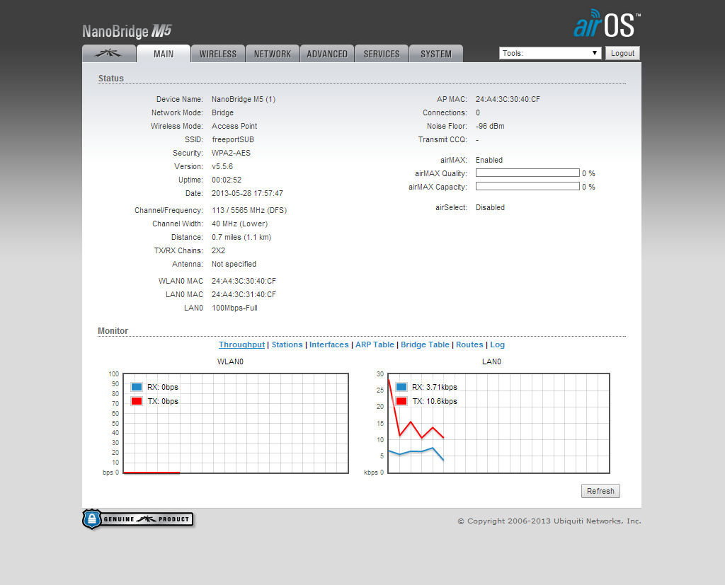
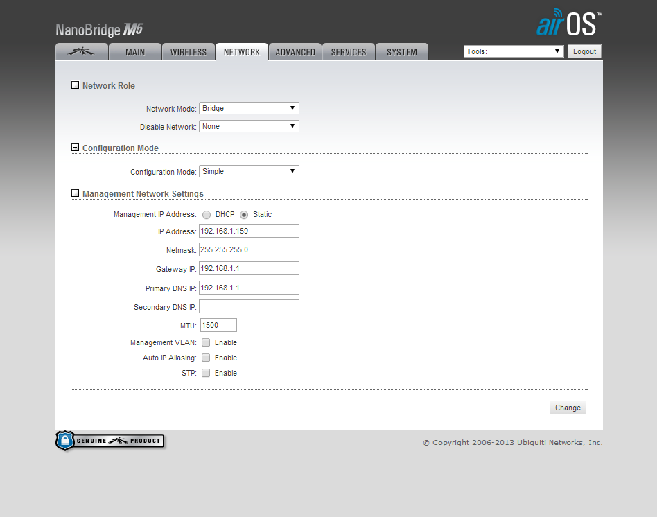
When you are done, your settings should look something like these:

Access Point:


Station:


If the two units show red status lights, then they are connected and the link is complete. Packets can be sent to the IP address of the opposite computers Ethernet port via the console command ping 192.168.1.x This should return data.

Our next post will show how we used this network connection to create a private network in order to communicate with the electronics on the submersible.