Our idea for a submersible is one that is both an ROV (remotely operated vehicle) and an AUV (autonomous underwater vehicle). We want an ROV with AUV capabilities because it allows the user a diverse array of capabilities. The user could choose to explore a fishery with the ROV, but then anchor the robot, and have it stationed overnight. To do this we need an Inertial Measurement Unit (IMU) to accurately measure the direction and angle of submersible in many different directions. We chose to use the Razor IMU which is going to measure the difference in Yaw, Pitch, and Roll for the submersible. That information will then be relayed to the Raspberry Pi (or any other computer) which will be able to compensate for said movement. Before doing any of this we needed to setup the IMU. The following materials are needed to setup your own Razor IMU.
The IMU we chose to use is the
Razor 9DOF IMU from
SparkFun Electronics. We chose to use this board because it has a lot of documentation on the internet and free code showing how to set it up. The Razor was $125.00 and therefore we had to do a lot of research before buying this product (one should also look at the other choices and what works best for their project), but we concluded that the Razor gave us the most bang for our buck. The Razor also needs a
FTDI Basic Breakout (3.3v) board, a Mini USB cable, and a
JST Jumper Wire for power (which, unfortunately, has to come from SparkFun or it
will not fit). Pictures of the hardware are below:
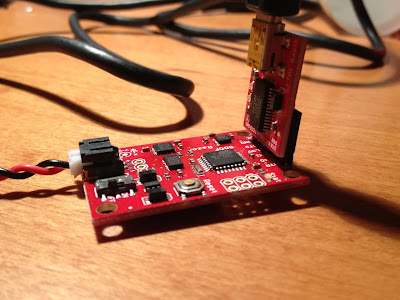 |
| JST to power, Razor, FTDI, and Mini USB |
After buying these products we followed
this very useful tutorial (the one we used to get our Razor working). One can either continue following our tutorial or refer to the site mentioned above.
After buying all of the hardware, downloading both the Arduino/Processing applications and the necessary firmware you only need to follow these steps to setup the Razor to give accurate Yaw, Pitch, and Roll readings.
The first thing we did was solder some pins onto the Razor for easy FTDI (if you are wondering, FTDI is just a brand name) connection. One can then plug in the FTDI 3.3v breakout board (make sure that that the pin inputs/outputs on the breakout are matched up to the right ones on the Razor!!) and the USB cable. Open the Arduino software and chose the Arduino board in the following picture. You should also open the Razor AHRS firmware package you downloaded from the link above (in the background).
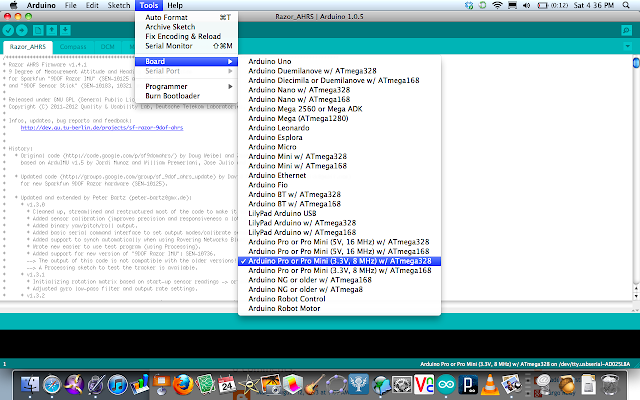 |
| Selecting the correct board with the Arduino AHRS file open in the background |
Once one has done this one can plug the Mini USB into the computer. Then choose the correct serial port by going to
Tools ---->
Serial Port.
FYI...the USB is able to supply power to the Razor...a battery or power source is not needed if plugged into a computer.
Next read up on the software (try to understand it and read through the beginning of the program. This is where the calibration data will be going).
Then one can upload the code and open the serial monitor from
Tools ---->
Serial Monitor and then choose a baud rate of 57600. One should see some uncalibrated degree measure for
YPR displayed like this:
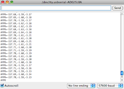 |
| Serial Port (Yaw, Pitch, and Roll) |
Next comes the calibration of the IMU. To do this enter
#oc in the serial window. This will show the accelerometer data. the accelerometer data. To calibrate it move the sensor very slowly in every direction. This will account for gravity (do NOT move it quickly or the accelerometer will give you very large numbers). Record the min/max for each value and save it for later.
 |
| example: not calibrated correctly |
Next enter
#on into the serial window. This will give one another calibration output. These numbers are the magnetometer readings. Now move the board in every direction as much as one wants and record the min/max values for the magnetometer (be careful doing this around laptops and other objects with magnetic fields...it may disrupt your data).
 |
| example: not calibrated correctly |
Lie the sensor on the table and enter
#on in the serial window to get ones final reading. These numbers are the average "noise" sensed by the gyroscope on all three axises (x, y, z). Record these min/max numbers.
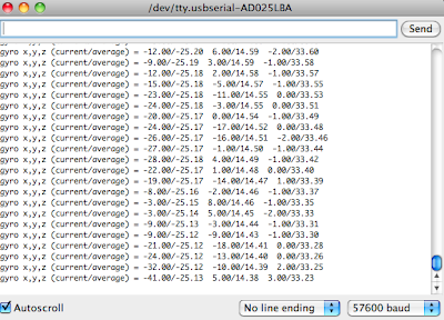 |
| example: not calibrated correctly |
If you would like to restart the calibration data type in
#oc and navigate back to the respective window by using the
#on command.
Once one is satisfied with that data a second magnetometer calibration must take place. To use this calibration method quite he Arduino software and open up
Processing 2.
Navigate to
Razor AHRS ---->
Processing ---->
Magnetometer Calibration and then open the .pde file.
Now put the IMU exactly where you will have it while using it to collect your data. This is very important because you need to calibrate the sensor in the same environment that it will be used in. After starting this software you should see something similar to this:
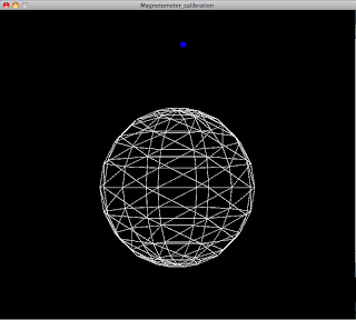 |
| extra Magnetometer calibration |
After you finish moving around the magnetometer as much as you can you'll have an image similar to this (the shape and size of the spheres/ellipses will depend on the amount of interference involved):
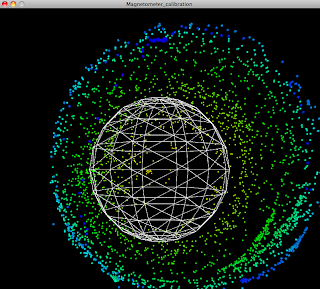 |
| Calibrating the magnetometer |
Once satisfied with your shape press the space bar, then exit the above window. Look at the serial output window at the bottom of the Magnetometer_Calibration window. Scroll through and look for outputs similar to these:
 |
| Magnetometer Calibration data |
Record them and then re-open Arduino and the Razor AHRS program.
Scroll down until you see commented lines for each of your data inputs (accel, mag, gryo, mag#2). Enter the numbers and then save and upload your changes to the Razor.† This should calibrate the Razor to your respective environment. You can easily recalibrate and we recommend doing it multiple times until you're sure that it's perfect.
If you would like to see the visual output of the IMU do the following.
- Quit Arduino
- Start Processing
- Open up Razor_AHRS_test through the Processing folder in the downloaded firmware package.
- Run the program. You should see an image similar to this:
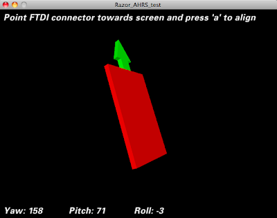 |
| Processing Razor_AHRS_test |
This image is not perfect...it will lag at some points. It's just cool to see an example of a visual output you can create using the Razor.
† The numbers should be relatively close to the example min/max values commented out in the .pde file. If they are greatly skewed in any way we recommend that you re-calibrate the sensor.


.jpg)


