11.28.2013

Xbox Controller Input with Java

There are several external Java libraries that can handle input from game-pads like the Microsoft Xbox controller. However, very few deal exclusively with the Xbox controller and many do not offer complete support. Thus, choosing the correct library is often a matter of the lesser of two evils.We found this library from www.aplu.ch that offers full support for all the buttons on the controller except the home button and is relatively simple to install. The full instructions and the download can be found here:


(installation and download on the right)

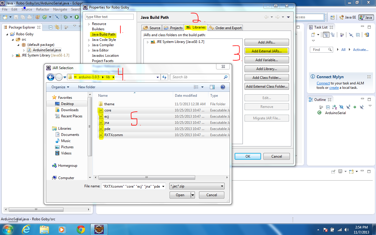
NB: as an alternative to placing the .dll files in a folder that is in your system file path (a process that can be difficult or tedious for those less used to more complicated computer work), the files can be directly referenced as the native code for the java libraries. This is done as follows:

1. Open the build path of your java project and open the drop-down menus of the two external jars you added for the Xbox Controller input, then select Native Library Location.

2. Navigate to the folder where both of the .dll files are located and select them.


The method these libraries use to collect controller input is very similar to the way the default Java libraries create Key Listeners. Here is a picture of our code (borrowed heavily from the tutorials posted on the afore mentioned site):


We start here by creating a instance of the XboxController object called xc and then in the constructor we initialize it  in a way in which we can detect whether the system the program is being executed on is 64 bit or 32 bit (using a ternary operator). We then check if the controller is actually connected to the computer and do not let the program start if it is not. Finally, we add a listener to the controller and pass it a new private nested class that extends the object XboxControllerAdapter. In this nested class, we define all the methods that will run when the various buttons on the controller are pressed. These are all specifically named and the full list of the names can be found in the javadoc section of the aplu website under XboxControllerAdapter:


Also, we set the dead zones of the two controller sticks so that they would not detect input until pressed to a certain degree. This is optional but helpful. Furthermore, one should not that frequent errors can occur with this library if it is used in tandem with too many swing components, such as JFrames and JWindows. It is therefore wise to keep ones listener in a class that can be run in a separate thread that is executed over and over. This allows the listener to be restarted if it crashes. Use a scheduled thread pool executor to manage the execution of your listener thread for Xbox input. 

NB: a more detailed example of how to implement this library can be found at the first link listed above at the bottom of the page.  


11.20.2013

Limbeck Engineering LLC

We have officially started our own company – Limbeck Engineering LLC. Our group is now an official company legalized by the State of Maine. This process took a while because we first had to research the different types of companies/non-profits and then find legal counsel. We came up with the rules for the shareholders in our company (voting, etc.) and then filled out a cover letter (conveniently attached to $175 for the State Department...). We learned a lot during this process and found that founding a company is not as hard as it sounds.

We have also started a fundraising campaign on Indiegogo and are looking for donations! Without money from supporters we will never be able to finish out project!

Our campaign can be found here: http://igg.me/at/robogoby/x/5401528


11.13.2013

ESCs with Raspberry Pi and Arduino Uno

After finishing our mechanical testing and seeking some advise, we decided to test some brushless motors. In order to do this we needed to setup (one or more) ESCs. ESCs are motor controllers, but are different from the one used in this post. Instead of using PWM to alternate the voltage to the motors directly, ESCs use PWM to alternate voltage between 3 different magnetic plates at 120° intervals.

We decided to test these motors for 2 major reasons. For one, the out-runner brushless motors have high tork for their size. Secondly, brushless motors are waterproof (if the wires are sealed directly) and therefore we do not need to build a waterproof container for them. Below are the steps we used to initialize our ESCs to use the brushless motors. 

Hardware:

Software:

Raspberry Pi

1. Download ServoBlaster using git:


2. Install the ServoBlaster module kernel:


3. Make the ServoBlaster nod:


4. Know you can echo commands to the /dev/servoblaster file (echo "5=150" > /dev/servoblaster). Check out the README from the ServoBlaster link above. Use this image to help you attach the wires to the correct spot on the GPIO pins (make sure to only use ground and data):

RPi revision #2

5. To use the ESC, first fasten the motors to something (like a piece of wood) and attach the ESC. Then cut the R/C receiver and peel off the black and white wires (leave the red one alone). Twist the data and ground wires from the ESC and Pi together. It should now looking something like this:

Brushless Motor
30A ESC w/Radio output

6. Next, set ServoBlaster to neutral by sending this command:


7. Turn on the ESC and wait for a few short beeps. This means that the controller has detected the neutral signal. Once you've done this you can set the max and min speeds as well as braking power using the manual that came with your motor (if you have a similar LED programmable board to the one we have).


Arduino

The Arduino setup and code we used is based off of this tutorial.

1. Download the latest Arduino IDE and the Arduino Brushless ESC code.

2. Using the analog dial, breadboard, ESC, and Arduino wire them as follows (and do not plug in the 5v ESC wire to the Arduino!!...if both the USB and 5v from the ESC are used you will fry the Arduino). This code allows the Arduino to take the analog voltage variation from the dial and convert it to digital PWM signals which then control the ESC.


our setup using the above diagram looks like this:


3. To program the ESC this way, find the neutral value of your controller (using a volt meter measuring from ground to digital PWM) and then follow the directions in the manual provided with your specific controller. Also make sure to have the correct pin values in your Arduino code (this gets a lot of people) and triple check your breadboard connections (this got us!).  Here is an example of the code:


Note: ServoBlaster on the Raspberry Pi is very reliable and works every time. The Arduino not so much...you might have to play around with it a little bit (it has a hard time finding neutral and the Arduino may not read the full range of the dial). Don't get discouraged though – it will work eventually.


11.10.2013

Java + Arduino Serial on Raspberry Pi ( & Windows 7)

Over the summer we were able to read serial outputs from the Arduino using Python on the Raspberry Pi. Realizing that if we wanted our entire Project Repository to be written in Java, we had to find another way of reading data from the Arduino. By downloading the Arduino Libraries and then adding them to your Eclipse Project, you should be able to read the serial outputs from the Arduino. After getting the Arduino working on your PC, we will change the code slightly to work on the Raspberry Pi.

This is an example from Arduino.cc. This has some problems with it and we would recommend that you follow our example below.

Software: 
  • Eclipse
  • Latest Arduino IDE (need the .jars) 
    • use this link for steps on how to download the Arduino Drivers on Windows 7
  • RXTX 2.1-7 (for Raspberry Pi and 32 bit Windows)
  • RXTX 2.2 (for 64 bit Windows machine)
  • Java code found here (includes Client/Server configuration ----> very easy to change).
Windows 7:

1. Open Eclipse and then start a new project. 

2. Create a class called ArduinoSerial(). Import the .jars from the Arduino download into the Referenced Libraries found in the build path (example in the image below).

        • for 64 bit machines upload the RXTXcomm.jar from the link above.


3. Add rxtxSerial.dll and rxtxParallel.dll to your PATH (usually C:\Windows\system).


4. Download the Java our code (modified from this site). Copy n' Paste it into the ArduinoSerial() class. 

5. Change the communication port (COM, tty, etc). On Windows 7 it will be "COM x" (depending on which COM port you are using)

6. Upload a program onto the Arduino (use Baud 4800**)

7. Quit Arduino, and then run ArduinoSerial(). You should see this (text varies w/ Arduino code):


**on the Raspberry Pi a Baud rate of 4800 was ideal. It's a bug which needs to be worked out, but for now stick with 4800 bytes per second.


Raspberry Pi:

1. Change device name on ArduinoSerial. On the Raspberry Pi it will be "/dev/ttyAMA0". If you do not know which /dev device to use on the RPi follow the directions on the bottom half of this post.

2. Reconfigure the RXTXcomm.jar in the above example and use the Arduino IDE version.

3. Export the ArduinoSerial() class as an executable JAR. Copy it onto the RPi's desktop.


4. Download the Linux version of RXTX library with this command (downloads RXTX 2.2pre2):


5. Copy the Linux folder from the RXTX 2.1-7 download to the /tmp folder on the Raspberry Pi.

6. Copy the RXTXcomm.jar file from the above into /tmp.

7. CD into the Java Virtual Machine library PATH (/usr/lib/jvm/java-7-openjdk-common/jre/lib) and move the Linux folder into it.


8. Then cd into /ext and move the RXTXcomm.jar into it.


9. Plug in the Arduino the the Raspberry Pi. Run the executable file on the Desktop.


10. You Should see something like this (the Arduino is sending temperature readings):


As you can see the libraries are mismatched. This goes away if you use the RXTXcomm.jar 2.2pre2.

For some reason the RXTX download on Qbang says it's 2.2pre2, but it is actually 2.2pre1....what!?

11.03.2013

Arduino Uno: Hall Effect Sensor

While brainstorming ideas for our float, we stumbled upon a problem. How would we be able to calculate the length of the tether in the water? We thought of a few different ideas, but nothing very feasible. One day someone mentioned the Arduino Hall Effect Sensor to us. The Hall Effect is used in things such as bicycle speedometers. It uses the diameter of the wheel and calculates the speed of the rider by timing how long it takes for the sensor to make one rotation.

Hall Effect Sensor
1. We used the UA Package Hall Effect sensor. For more information visit this sheet. A sketch of the sensor and chart explaining which wires connect to the Arduino is below:


1. Hook up three wires (red, black, and blue) to the sensor and to the Arduino Uno. Connect the red wire to 5v, the black wire to GND, and the blue wire to Analog 0.  After making sure the connections are correct and you're ready to rock!


3. The code we modified for our tether spool was found here. If you would like to see the code we used go here and find the folder named Arduino - Hall Effect Sensor. Upload it to your Arduino Uno and then view the serial monitor. Every-time the magnet passes the sensor you should see this: