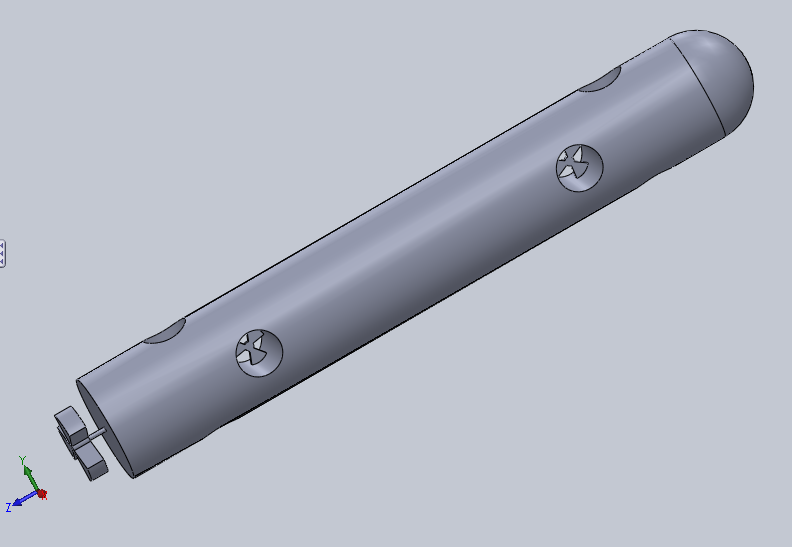
12.18.2013

Initial Body Designs

For the past couple of weeks we have brainstormed a few basic designs for our submersible. Currently we are trying to choose a design to pursue. This process is harder than we thought – the idea of having to commit to a design for the rest of the project is a daunting task. Thus we are writing this blog post to give an idea of what the ROV may look like.

Please comment with any thoughts on the designs!

Design 1

The forerunner of the three designs look a bit like your regular submarine:

Isometric View

Top View


PROS:
  • Smallest frontal surface area
  • Precise control of everything but roll
  • One large motor and one large prop (takes less power and is overall more efficient)
  • Easily add new capsules (storage, experimental instruments, etc.) simply by elongating the ROV
CONS:
  • Small volume in which to fit stereoscopic cameras
  • No control of roll
  • Large side profile

Design 2

This design we called the winged sub (as you can probably see why). The two wing thrusters will be able to rotate (using servos), giving us most of our desired degrees of freedom:


Isometric View
Top View
Elevated Back View


PROS:
  • Medium amount of frontal surface area
  • Two large motors (better maneuverability and thrusting force)
  • Fewest thrusters
  • Control of all 5 degrees of freedom (including roll) 

CONS:
  • No strafing (must always be moving nose-first)
  • Needs servo motors for variable thrusters (another layer of complication)
  • Small volume in which to fit stereoscopic cameras

Design 3

The final design it to connect two identical cylinders:

Isometric View

Top View


PROS:
  • Two large motors (better maneuverability and thrusting force)
  • Control of all 5 degrees of freedom (including roll)
  • Two separate capsules for stereoscopic cameras

CONS:
  • Largest frontal surface area
  • Largest number of thrusters

Limbeck's Endeavors: New Blog

In light of other engineering "Endeavors" Limbeck Engineering will be apart of this year, we have started a new Blogger site. Although most of our work will be done on the submersible, we will also be working on completing an open source 3D Printer, variable pitch Windblade design, and tug of war robot.

Check out our new blog at:


12.01.2013

Overlay for VLCJ Embeded Media Player

There are many methods to create a transparent overlay for a VLCJ Embedded Media Player. Few, however, allow dynamic updating of swing components.


To create an overlay for a VLCJ media player window that can display dynamically updated data through Swing components, such as JLabels, you will need to begin by creating a nested class that extends JWindow, as shown here:

The only things that are required here are the extension of the class JWindow, the constructor, the super call, the call of AWTUtilities to set the window opaque, and the call to set layout to null.

The next step can be done in the constructor of the player class which you have used to create your media player. First create three global variables:


Then, these lines must be added to the constructor:


Altogether, these lines will specify your nested overlay class as the overlay for the VLCJ media player you created with EmbeddedMediaPlayer. 

A few specifics: 
  • the instance of the overlay class you create must be passed the JFrame that contains the Canvas declared later (whether this is your Player class itself or an object created within it, as it is here); 
  • the Canvas created here is the holder for your media player and its overlay; 
  • the setOverlay method will cause your Overlay class to be painted over the media player at run-time. 
With this done, all one has to do to have a swing component painted over the player is add it to the Overlay class in its constructor with a call of the add() method. A good way to do this is to create the swing components as static objects in the Player class so that they can be accessed by and changed throughout the program.

11.28.2013

Xbox Controller Input with Java

There are several external Java libraries that can handle input from game-pads like the Microsoft Xbox controller. However, very few deal exclusively with the Xbox controller and many do not offer complete support. Thus, choosing the correct library is often a matter of the lesser of two evils.We found this library from www.aplu.ch that offers full support for all the buttons on the controller except the home button and is relatively simple to install. The full instructions and the download can be found here:


(installation and download on the right)

NB: as an alternative to placing the .dll files in a folder that is in your system file path (a process that can be difficult or tedious for those less used to more complicated computer work), the files can be directly referenced as the native code for the java libraries. This is done as follows:

1. Open the build path of your java project and open the drop-down menus of the two external jars you added for the Xbox Controller input, then select Native Library Location.

2. Navigate to the folder where both of the .dll files are located and select them.


The method these libraries use to collect controller input is very similar to the way the default Java libraries create Key Listeners. Here is a picture of our code (borrowed heavily from the tutorials posted on the afore mentioned site):


We start here by creating a instance of the XboxController object called xc and then in the constructor we initialize it  in a way in which we can detect whether the system the program is being executed on is 64 bit or 32 bit (using a ternary operator). We then check if the controller is actually connected to the computer and do not let the program start if it is not. Finally, we add a listener to the controller and pass it a new private nested class that extends the object XboxControllerAdapter. In this nested class, we define all the methods that will run when the various buttons on the controller are pressed. These are all specifically named and the full list of the names can be found in the javadoc section of the aplu website under XboxControllerAdapter:


Also, we set the dead zones of the two controller sticks so that they would not detect input until pressed to a certain degree. This is optional but helpful. Furthermore, one should not that frequent errors can occur with this library if it is used in tandem with too many swing components, such as JFrames and JWindows. It is therefore wise to keep ones listener in a class that can be run in a separate thread that is executed over and over. This allows the listener to be restarted if it crashes. Use a scheduled thread pool executor to manage the execution of your listener thread for Xbox input. 

NB: a more detailed example of how to implement this library can be found at the first link listed above at the bottom of the page.  


11.20.2013

Limbeck Engineering LLC

We have officially started our own company – Limbeck Engineering LLC. Our group is now an official company legalized by the State of Maine. This process took a while because we first had to research the different types of companies/non-profits and then find legal counsel. We came up with the rules for the shareholders in our company (voting, etc.) and then filled out a cover letter (conveniently attached to $175 for the State Department...). We learned a lot during this process and found that founding a company is not as hard as it sounds.

We have also started a fundraising campaign on Indiegogo and are looking for donations! Without money from supporters we will never be able to finish out project!

Our campaign can be found here: http://igg.me/at/robogoby/x/5401528


11.13.2013

ESCs with Raspberry Pi and Arduino Uno

After finishing our mechanical testing and seeking some advise, we decided to test some brushless motors. In order to do this we needed to setup (one or more) ESCs. ESCs are motor controllers, but are different from the one used in this post. Instead of using PWM to alternate the voltage to the motors directly, ESCs use PWM to alternate voltage between 3 different magnetic plates at 120° intervals.

We decided to test these motors for 2 major reasons. For one, the out-runner brushless motors have high tork for their size. Secondly, brushless motors are waterproof (if the wires are sealed directly) and therefore we do not need to build a waterproof container for them. Below are the steps we used to initialize our ESCs to use the brushless motors. 

Hardware:

Software:

Raspberry Pi

1. Download ServoBlaster using git:


2. Install the ServoBlaster module kernel:


3. Make the ServoBlaster nod:


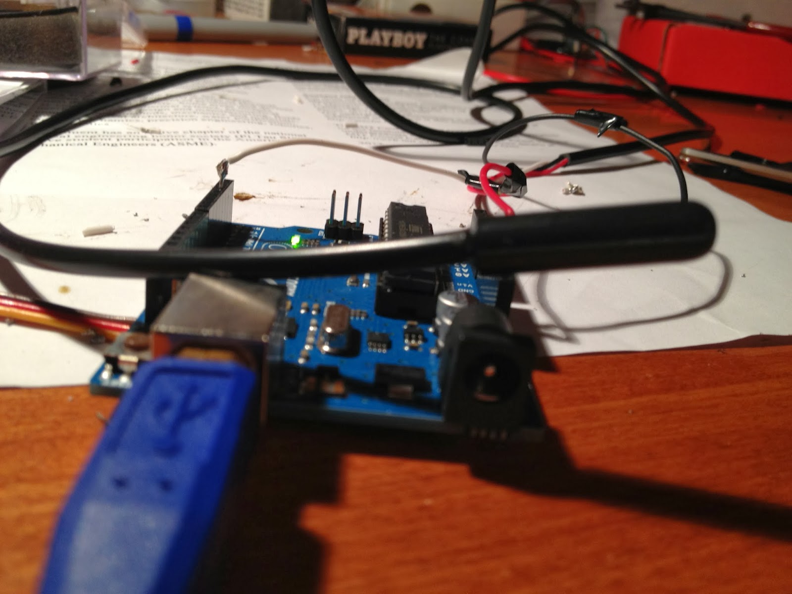
4. Know you can echo commands to the /dev/servoblaster file (echo "5=150" > /dev/servoblaster). Check out the README from the ServoBlaster link above. Use this image to help you attach the wires to the correct spot on the GPIO pins (make sure to only use ground and data):

RPi revision #2

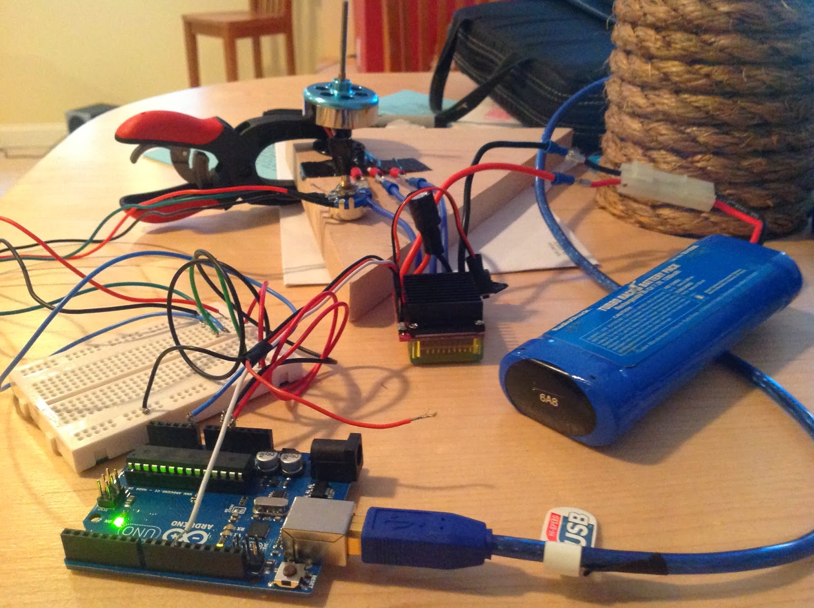
5. To use the ESC, first fasten the motors to something (like a piece of wood) and attach the ESC. Then cut the R/C receiver and peel off the black and white wires (leave the red one alone). Twist the data and ground wires from the ESC and Pi together. It should now looking something like this:

Brushless Motor
30A ESC w/Radio output

6. Next, set ServoBlaster to neutral by sending this command:


7. Turn on the ESC and wait for a few short beeps. This means that the controller has detected the neutral signal. Once you've done this you can set the max and min speeds as well as braking power using the manual that came with your motor (if you have a similar LED programmable board to the one we have).


Arduino

The Arduino setup and code we used is based off of this tutorial.

1. Download the latest Arduino IDE and the Arduino Brushless ESC code.

2. Using the analog dial, breadboard, ESC, and Arduino wire them as follows (and do not plug in the 5v ESC wire to the Arduino!!...if both the USB and 5v from the ESC are used you will fry the Arduino). This code allows the Arduino to take the analog voltage variation from the dial and convert it to digital PWM signals which then control the ESC.


our setup using the above diagram looks like this:


3. To program the ESC this way, find the neutral value of your controller (using a volt meter measuring from ground to digital PWM) and then follow the directions in the manual provided with your specific controller. Also make sure to have the correct pin values in your Arduino code (this gets a lot of people) and triple check your breadboard connections (this got us!).  Here is an example of the code:


Note: ServoBlaster on the Raspberry Pi is very reliable and works every time. The Arduino not so much...you might have to play around with it a little bit (it has a hard time finding neutral and the Arduino may not read the full range of the dial). Don't get discouraged though – it will work eventually.


11.10.2013

Java + Arduino Serial on Raspberry Pi ( & Windows 7)

Over the summer we were able to read serial outputs from the Arduino using Python on the Raspberry Pi. Realizing that if we wanted our entire Project Repository to be written in Java, we had to find another way of reading data from the Arduino. By downloading the Arduino Libraries and then adding them to your Eclipse Project, you should be able to read the serial outputs from the Arduino. After getting the Arduino working on your PC, we will change the code slightly to work on the Raspberry Pi.

This is an example from Arduino.cc. This has some problems with it and we would recommend that you follow our example below.

Software: 
  • Eclipse
  • Latest Arduino IDE (need the .jars) 
    • use this link for steps on how to download the Arduino Drivers on Windows 7
  • RXTX 2.1-7 (for Raspberry Pi and 32 bit Windows)
  • RXTX 2.2 (for 64 bit Windows machine)
  • Java code found here (includes Client/Server configuration ----> very easy to change).
Windows 7:

1. Open Eclipse and then start a new project. 

2. Create a class called ArduinoSerial(). Import the .jars from the Arduino download into the Referenced Libraries found in the build path (example in the image below).

        • for 64 bit machines upload the RXTXcomm.jar from the link above.


3. Add rxtxSerial.dll and rxtxParallel.dll to your PATH (usually C:\Windows\system).


4. Download the Java our code (modified from this site). Copy n' Paste it into the ArduinoSerial() class. 

5. Change the communication port (COM, tty, etc). On Windows 7 it will be "COM x" (depending on which COM port you are using)

6. Upload a program onto the Arduino (use Baud 4800**)

7. Quit Arduino, and then run ArduinoSerial(). You should see this (text varies w/ Arduino code):


**on the Raspberry Pi a Baud rate of 4800 was ideal. It's a bug which needs to be worked out, but for now stick with 4800 bytes per second.


Raspberry Pi:

1. Change device name on ArduinoSerial. On the Raspberry Pi it will be "/dev/ttyAMA0". If you do not know which /dev device to use on the RPi follow the directions on the bottom half of this post.

2. Reconfigure the RXTXcomm.jar in the above example and use the Arduino IDE version.

3. Export the ArduinoSerial() class as an executable JAR. Copy it onto the RPi's desktop.


4. Download the Linux version of RXTX library with this command (downloads RXTX 2.2pre2):


5. Copy the Linux folder from the RXTX 2.1-7 download to the /tmp folder on the Raspberry Pi.

6. Copy the RXTXcomm.jar file from the above into /tmp.

7. CD into the Java Virtual Machine library PATH (/usr/lib/jvm/java-7-openjdk-common/jre/lib) and move the Linux folder into it.


8. Then cd into /ext and move the RXTXcomm.jar into it.


9. Plug in the Arduino the the Raspberry Pi. Run the executable file on the Desktop.


10. You Should see something like this (the Arduino is sending temperature readings):


As you can see the libraries are mismatched. This goes away if you use the RXTXcomm.jar 2.2pre2.

For some reason the RXTX download on Qbang says it's 2.2pre2, but it is actually 2.2pre1....what!?

11.03.2013

Arduino Uno: Hall Effect Sensor

While brainstorming ideas for our float, we stumbled upon a problem. How would we be able to calculate the length of the tether in the water? We thought of a few different ideas, but nothing very feasible. One day someone mentioned the Arduino Hall Effect Sensor to us. The Hall Effect is used in things such as bicycle speedometers. It uses the diameter of the wheel and calculates the speed of the rider by timing how long it takes for the sensor to make one rotation.

Hall Effect Sensor
1. We used the UA Package Hall Effect sensor. For more information visit this sheet. A sketch of the sensor and chart explaining which wires connect to the Arduino is below:


1. Hook up three wires (red, black, and blue) to the sensor and to the Arduino Uno. Connect the red wire to 5v, the black wire to GND, and the blue wire to Analog 0.  After making sure the connections are correct and you're ready to rock!


3. The code we modified for our tether spool was found here. If you would like to see the code we used go here and find the folder named Arduino - Hall Effect Sensor. Upload it to your Arduino Uno and then view the serial monitor. Every-time the magnet passes the sensor you should see this:


10.20.2013

Java Socket Server/Client on Raspberry Pi

In order to connect to the Raspberry Pi, we've been using either a secure shell login (ssh) or a virtual desktop (VNC). These capabilities allow to us download software and test different code vital to our project. What these do not allow is instant communication through a Java Program. Socket servers/clients will allow us to open up different ports on the Raspberry Pi and wirelessly stream data through them. For example we could open up a port that wirelessly writes numbers to a Pi-Blaster file, therefore controlling our motors.

A socket server program listens to a port. When a client tries to connect the server either allows it in or denies it access to the port. If allowed access the client and server can now communicate using UDP/TCP communication protocols.

Below is a quick explanation and example of using Socket Severs/Clients on the Raspberry Pi for PWM control.

Sockets Running Pi-Blaster:

Sending strings back and forth between a client and server uses simple InputStream()/OutputStream() commands. We needed to be able to send strings and then have them echoed to /dev/pi-blaster (command line virtualization). We had some trouble echoing commands using 'bash' from a Java program. We eventually figured it out using a Java program and Shell Script on the Raspberry Pi.

We first sent PWM values to a file called motorcontrol.sh and then use Runtime() in Java to emulate a 'bash'  command. The following is the Shell Script which 'echos' are the values we give it to /dev/pi-blaster.

The code for the Server and Client can be found on our Downloads page under Java - Socket Server.

Edit the IP address in the Client.java and Server.java files to match you specific IP requirements.

After exporting the server into a runnable .jar file copy it to the Raspberry Pi and then run it using this command:


Next run the Client on your laptop (we are just using Eclipse for now). It should look something like this:


and you have a Client/Server connection to the Raspberry Pi to run Pi-Blaster! Stay updated for instructions on how to use an XBox Controller to send values (instead of a JOptionPane).


10.19.2013

Arduino Sensor: DS18B20 1-Wire Temp. Probe

This is the first of many posts which deal with setting up the environmental sensors on our submersible. The first sensor we experimented with was the DS18B20 Waterproof Temperature Sensor. This sensor was extremely easy to setup and therefore a good start for us.

We also decided to choose this temperature sensor because of its diverse capabilities. The DS18B20 is designed on a "1-Wire" data transfer technique. This allows for the easy addition of multiple temperature sensors on one Arduino.

Materials Needed:

  • Arduino UNO (and Arduino software)
  • DS18B20 Waterproof Temperature Sensor
  • 4.7k ohm resistor (***make sure it is 4.7k ohm NOT 4.7 ohm)
  • Wire cutters/strippers and electrical tap
  • Solder

1. Visit our Download Page and download our code + libraries in the folder: Arduino - DS18B20

2. Download the libraries and then move them into Documents---->Arduino---->Libraries (may have to make  the library folder).

3. Acquire a DS18B20. There will be three different wires (white=data, red=power, black=ground)

4. Stip off the waterproof casing from the first 6 inches of the sensor.

5. Cut both the power and data wires about 1 inch from the end of the casing.

6. Solder one side of the resistor onto the data wire and the other side to the power wire.

7. Solder on pins to the end of each sensor wire.

8. A picture of the final product is below (we recommend wrapping the open wire in electrical tape):


and this is a sketch of the setup we used (yellow=data):


and here is a picture of the sensor and our Arduino. 


9. Upload the code to the Arduino. You should see a serial monitor output (baud 9600) like this:


Stay updated for tutorials on how to use Java to display Serial Outputs from the Arduino over the Video Stream. To output the data using Python on the Raspberry Pi check out the Arduino UNO: Serial Outputs to Raspberry Pi. To use the DS18B20 through Java check out this post.

10.18.2013

RoboGoby T-Shirt

For the past week and a half we have been coming up with ways to fundraise for our project. We have been working on an Indiegogo campaign that we will publish soon. We have also met with a few local businesses. We also came up with the idea of using t-shirts sales as fundraiser/promotion gig. We spent a while deciding what the shirt would look like. Today we finalized the image and the text on the front of the shirt.  We have decided to have a robotic looking fish that is modeled after a Goby, as well as the words, "Project RoboGoby."

Project RoboGoby Fundraising T-shirt
The entire thing was made by Nick in Photoshop Elements 8, though some pieces were modified from pictures found online. Everyone please give a BIG shout-out to Nick – he spent a ton of time on this design.

The basic shape of the fish is modeled after the dimensions and fins of a goby. We decided that the most important robotic parts would be: gears, propellors, sensors, and lights/cameras. In the end we decided to make it look fairly simple so the design isn't too overwhelming for the observer (edited out a lot of the extra material). The shirt is blue to represent underwater and the fish is green mostly because it stands our on a blue back ground. The fish is made of 28 different layers.

The back of the shirt is going to have the phrase: "Limbeck, I don't know what it means either." This is because we are always asked how we came up with the name and what it means. We are also going to order four shirts for ourselves with backs that say: "Head Engineer."

If you are interested in buying one, please fill out the form at the bottom of this page. They cost $20 plus shipping and handling ($3).

Embedding Video with VLC Media Player


VLC has a handy Java library that can be used to create an instance of the VLC media player that can be embedded in a separate Java program. This player will play any media that VLC player can play independently if it is given the correct file path to that media as well as the location to the pre-downloaded VLC libraries. This includes media streams from other devices such as internet servers. This API (Application Programming Interface) is very useful for designing your own media player in which your GUI (Graphical User Interface) foundation is a functional media stream. It is also relatively easy to set up.


  1. http://www.videolan.org/vlc/download-windows.html go to this link and download the appropriate system architecture version of the VLC installer for your operating system (64-bit or 32-bit). It is important to get the bit number right as a 32-bit VLC will not work for a 64-bit system and vice versa. 
    • make sure to note the location of the VLC folder containing its files (usually something like C:\Program Files\VideoLAN\VLC)
  2. http://www.capricasoftware.co.uk/downloads/index.html go to this website and download the latest vlcj distribution zip. Extract this to a folder of your choosing. 
  3. Open up Eclipse (we use Eclipse but if you understand how import external libraries in a different IDE then use that). Create a new project and right click on it. Select the "build path" option then select "configure build path"
  4. In the resulting window, select "add external jars" and navigate to the vlcj distribution you downloaded in step 2. Select the "jna.jar," "platform.jar," and "vlcj.jar" (note: each of those will have a version number in the name).
From there, you will need to point your program toward the VLC folder mentioned in step 1 as well as the media file you want to play. http://www.youtube.com/watch?v=orMgNh0o38A This video does a very good job of describing the basic procedure of coding a media window to play a file pointed to during run time. in order to play a video stream, you must replace the argument for 

"mediaPlayer.getMediaPlayer().playMedia()"

with the url of the stream (what you might enter into a web browser to view the stream). For the MJPG-streamer software that we use, this is a little different. We pass the string 

"http://[local ip adress of stream]:port/?action=stream"

Our code for the media player will be on our Github and a link will be posted soon. 

10.17.2013

Mechanical Testing: Motor and Prop Testing


After creating our testing tank and our setting up our sensors (for volts, amps, and newtons) we started to actually test the motors. It took about an hour to test each motor with the corresponding props in both forwards and reverse. Although the whole process took much longer because we had to try motors multiple times and we were often distracted by other parts of the project.

To test the motors we put them into our (not so much) waterproof container. We ended up flooding this container because some of the motors moved to much and caused flooding. Therefore, we had to create a constant (which was our container) to test the motors in. It was a challenge to get some of the motors into our container (particularly the Rule 1000GPH and Rule 800GPH, which we had to "carefully" force in). Another complication was making sure that the wires were fed up through the pipe to the surface of the water and were not too twisted or submerged. The rod in the top of the tank was then threaded through the pipe to act as the fulcrum of our lever. We then connected non-stretch fishing line that ran from the force plate, through the pulley and to the pipe, we had to tie it so that it was continually pulling on the container (because it would have been very hard to zero it perfectly by tying it...). We then zeroed it using Logger Pro. Lastly we connected the motors wires to the motor controller and then the controller to the battery.

The first picture below is of our testing tank from a ground perspective. The Raspberry Pi is in the foreground and the tank with the our motor controller and battery are in the background. The second picture is a front view of the tank we used for testing:


After that we had to set up the equipment for reading the data. We connecter the Vernier force plate we were using to our computer through a Lab Pro and into LoggerPro, from this we got force readings to the nearest newton (setup pictured above). To get amperage readings we used a Blue Point CAT III amp clamp connected to a Vantage graphing voltmeter. Finally for voltage we used another more basic voltmeter. We had to record our data in a google spread-sheet and then transfer it to Logger Pro because of some program limitations.

To test we needed to SSH into the Raspberry Pi and used Pi-Blaster (a PWM program) to control the motor through our motor controller. Setting PWM duty cycle signals to 25%, 50%, 75% and 100% to get a quarter, half, three-quarters and full power respectively. At each of these presets we took readings of voltage, amperage and force. We then switched out the propellor which was easy thanks to our propellor attachment design. After we had finished using all ten of our chosen propellors we would switch the direction of the entire container by switching its direction on the rod in the other direction and switching a double pole, double throw switch to change the direction of the electricity. We than ran through all of the propellors in forward and reverse giving us twenty-four data points for each test. We tested 10 different props and 3 different motors giving us a total data point set of 720.

10.13.2013

RPi Video Streaming: MJPG-Streamer

MJPG-Streamer was the last pre-built video streaming software we tested. It was something that we had looked into earlier in the summer, but had never followed through with. It is comparatively "lighter" than both Ffmpeg and Motion. It was fairly easy to download and compile although you do have to jump through a few loopholes.


 1. Use your laptop to download and unzip the MJPG-Streamer software.

 2. Forward the folder from your desktop using a secure shell connection (scp forwarding).


3. Login to your Raspberry Pi and download the following dependencies.

--------> Update the Raspbian Operating System
       
--------> Install dependencies (libv4l-dev, subversion, libjpeg8-dev, imagemagick)


4. Copy the following file to a different name (MJPG-Streamer will show a make error otherwise). Try this a few times as it may not work correctly the first time.


5. Then, just for good housekeeping, Clean All and then run the Makefile.


7. Now you're ready to stream using MJPG-Streamer. Enter the following command. It will hopefully inform you that the stream is up and running. Our stream is running at 20 frames per second, at a resolution of 1280x960 pixels on the port 8092.


To customize the settings (fps, resolution, and device) you can change the values that follow these letters:


8. To view your stream open up Firefox (or Chrome) and type in the ip of the Pi followed by the port # (i.e. http://10.0.1.201:8082). You should see the following:


9. Obviously you will not always want to view your stream over this page. To view this same stream directly open VLC and type in the following:


The direct stream should look like this:


After long nights testing different camera's and there capabilities we finally found one worth the effort. MJPG-Streamer is the best universal USB video streaming software we've used. We would recommend this over Motion and Ffmpeg because of its fluidity and response time. 
To see how we have integrated MJPG-Streamer into a friendly Java GUI check out this post.