9.26.2013

Mechanical Testing: Designing our Testing Tank #2

After spending many hours testing our motors and props we realized that the setup of our up old testing tank was not acceptable. The force sensor we used (Vernier up to 50 Newtons) was not strong enough for our motors. We were producing more then 50 Newtons of force (about the equivalent of 10 pounds of force) and therefore could not graph and represent the different motors and props accurately.

The new design for our tank is shown below. Instead of using a 50N sensor we are using a 300N sensor attached to our container by a tether. The amount of force that the motors create is then recorded by measuring the tension on the force plate. To make sure the entire plate wasn't lifted off of the table we added 26 lbs. and zeroed our scale.


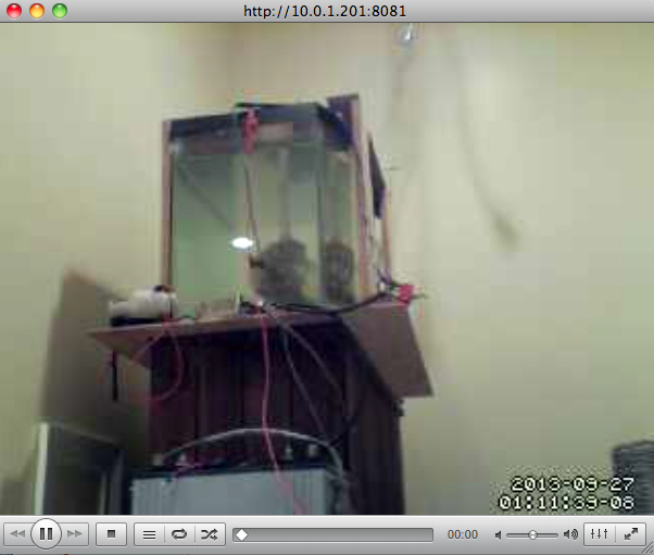
Re-designed Testing Tank 

We attached a strong piece of non-stretch finishing line (from trusty L.L.Bean, right around the corner) to the top of our PVC. The force is then redirected to the force plate using the pulley pictured below. The pulley is suspended between two pieces of wood cut to form a triangle. We designed it so the  altitude of the triangle was as small as possible and then added small wooden braces to strengthen the design. A picture of this setup is shown below:

New pulley system

To test the motors in reverse we simply turn the container around and attached the PVC to the tether the opposite way. The tether and force plate stay attached and works in the same way it did while testing the motors forward. 

While testing our motors we are going to record the voltage, amperage, and force that each motor/prop combination creates. This data will help us in the future with choosing the types of batteries we need for the ROV as well as the best motors to use in the submersible. Our next post will show some our results from the tests.

9.19.2013

RPi Video Streaming: Ffmpeg/Ffserver

Ffmpeg is the other video streaming software we used on the Raspberry Pi. We chose to experiment with this software because of its extensive documentation online (here). We also chose to use Ffmpeg because of it's streaming capabilities. Unlike Motion, Ffmpeg has Java streaming capabilities already built into Java syntax. Since our UI is going to be written entirely (well, almost entirely) in Java we thought that having a simple code to grab images from the Pi would be useful. One of the drawbacks to Ffmpeg is its size. Ffmpeg is massive and therefore runs into problems while trying to stream on the Pi. It has hundreds of options which can be changed for your liking. We made up our minds on it's usefulness pertaining to our project, but first check it our for yourself.

The compiling and configuration of Ffmpeg is more difficult than for Motion, but if you follow the directions below it shouldn't be a problem

Download:

1. VLC


Compiling:

1. Add the following sources to your /etc/apt/sources.list page


2. Update the Pi (I know this is the umpteenth time you've updated, but it is a good way to make sure your code doesn't cause you any problems)


3. Download dependencies


4. Remove the second line you added above (it should look line the screen below)


5. Download the source code.


6. cd into the ffmpeg directory


7. Configure and install


Configuration:

1. Create a file in /etc called ffserver.conf


2. Add configuration settings (similar to the ones below). You can change these in a number of ways.


3. Now create a file in /usr/sbin called subcam.sh


4. And add this code:


5. Make it executable over the command line:


Running Ffmpeg:

1. Type in the following to start the server. The following stream output appear (2nd image)


2. Open up VLC and first navigate to the Open Network option and then type in the following url:

  • http://<my ip address>:8090/subcam.[video formate] (.asf, .swf, .mjpeg)


Navigating VLC
Opening up the stream


3. Now you have your ffmpeg stream! Yay!


Example Ffmpeg stream


Although Ffmpeg is great for many projects we realized that it is not right for ours. It has many capabilities that we do not need. This adds to the size of the program which is then related to the speed at which the Raspberry Pi can run it. The video we got using Ffmpeg was slow and laggey (not what we're looking for). Since this software did not work out for us we're going to try using MJPG-Streamer. It looks very promising. Stay updated to learn which streaming software we chose to use.

Raspberry Pi Video Streaming: Motion

After creating a wireless connection between the Raspberry Pi the next step was to download software to allow wireless video streaming over the internet through a webcam. The first step was to research the different types of software that are currently used on the Pi. The first, and easiest, video software was Motion. Downloading Motion on the Raspberry Pi was easy. After opening Terminal on VNC Viewer first update the RPi software by using this command:


Next download Motion by typing in this command:


Now you have to edit the software package you just downloaded. We used the editing software "nano", but you may use whichever one you are most comfortable with.

If you are using the same image as us you should find the package by following this file-path.


This command should open a very long page with a lot of writing on it. After we scrolled through and researched what to turn off and on, we came up with a list of our own:


  • Daemon = OFF to ON
  • webcam_localhost = ON to OFF
  • framerate = 100
  • webcam_port = 8081
Also make sure to go edit this file.

  • Turn Daemon streaming to YES
Now you can manually turn on Motion from the command line on the Raspberry Pi, but it should also startup on boot because the download automatically makes a file in /etc/init.d called motion. You can sudo nano it to see the file. To start Motion:

Command to start Motion
To view your webcam video go onto Firefox (seems to work the best on my laptop) and type in the IP address of the Pi:port number (xxx.xxx.x.x:8081). If you are connected to the same network as the Pi you should see an image on Firefox like this:

Motion streaming over Firefox

You can also use VLC by going to File ---> Open Network. This is shown below:

After doing that type in the IP address of the pi:port just as you did above.


Now you have another way to view the camera feed! Wahoo!

Motion streaming over VLC

2-Wire Tether: Data and Power

To control our submersible we need a way of transferring data from underwater to the surface. We looked into a number of different data transfer techniques and ended up choosing to control our robot over ethernet. After choosing to do this we had a major problem...how are we going to get 200 feet of ethernet cable and still have a light, flexible tether as well as power? And will the power cable effect our data? That much power flowing right next to a data cable can have catastrophic effects. We did some more research on different techniques and decided to use OpenROV's idea of a Two-Wire Tether. They had done a lot of the work for us so this choice was an easy one to make.

The idea behind this tether is that it will provide both power and data in 2-wires. It does this by using Ethernet over Power (EOP) adapters. These adapters were originally made for homes where wi-fi didn't have enough range or you cannot find long enough ethernet cords. You can plug these converters into  2 different outlets on opposite sides of your home. This allows for ethernet speed connection over larger distances and with lest instillation effort. Not surprisingly though this is the best way to transfer data and power below the surface of the water without much interference. A picture of EOP device attached to the Pi is below:

Ethernet Over Power (EOP) attached to a Raspberry Pi
Because we are not using a direct connection to a laptop setting up EOP was very easy. We just wanted to see if it would work. One end is plugged into the Pi and the other into a router. There are ways to attach the Ethernet directly from one computer to another, but as of right now we do not need to do that.

Check out other posts which show how we sent commands back and forth using EOP.

9.15.2013

Motor Controller + Raspberry Pi


After going through a lot of trouble trying to get Sabertooth 2x12 R/C motor controller working with the GPIO (General Purpose Input/Output) pins on the Raspberry Pi, we decided to use a basic motor controller from amazon (found here). The controller is pictured below. It has a simple dial (up to 12v) and is attached to a battery for use in our testing tank (motor controller on far right).

Testing tank (motor controller on far right)
After our testing was completed we took off the dial and attached the wires to the Pi. Soon after we had a motor controller which was capable of being turned on and off using the command line. To do this you can follow the steps below. First though, we need to explain exactly how this motor controller works.

Many motor controllers are attached to power and to a speed controller which has three wires – data, power, and ground. The speed controller can either be a dial, a lever, a computer, etc. The job of the speed controller is to vary of the Pulse Width Modulation signals (PWM signals) going into the motor controller. The duty cycle is how the pulse sizes are defined. They are measured in percentage which relates directly to the speed if the motor.

PWM Duty Cycle

Before jumping directly into the project we did some research on the different types of software/commands used to vary the PWM signals from the Raspberry Pi. We ended up finding a very reliable code which is capable of handling up to 8 controllers at once! It's called Pi-Blaster which is an updated version of ServoBlaster** and capable of controlling larger motors. The steps to install this software on the Pi are below. You can also follow the easy instillation process in Pi-Blaster link above.

1. Update Raspbian for good measure.


2. Get the source code using this git command:


3. Build it and then set it up to start on boot.


Now follow these quick steps to successfully attach the motor controller (we used) to the Raspberry Pi. The setup should be similar on any other device as long as it uses the same 1 data-wire setup.

1. Cut three wires – 1 red, 1 black, and 1 green.

2. Replace the dial controller with the wires cut above. It should look like the picture below:

3-wires attached on the left of the picture

3. Now attach the red wire to the 5v output on the Pi and the black ground. A picture of the GPIO setup on the Pi is below (Revision 2 which is Pi version B – look for revision 1 on the internet if you have a first generation RPi):


Revision 2
What our RPi 26 pin connector looks like (we would recommend using a ribbon cable/pin extension as  not to ruin the Pi's pins):

Data, Power, and Ground attached to RPi

4. The green wire has to go on one of the following pins. Using this chart and the diagram above attach the green wire to the Pi:

5. After connecting all of the wires, attach the motor and power supply to the motor controller.

6. Write these command into terminal. They forward the commands to /dev/pi-blaster which then uses them to send PWM signals.


  • To completely turn on Channel2(GPIO 18) 100%:

  •  To turn on Channel2 35%:


  • To turn off Channel2  (0%):


Here is a video of our motor controller and motor using these commands:


That's it! You can now use these commands to vary the speed of your motors for any type of project! Stay updated on our blog to learn how to write a simple program in which we will use arrow keys to speed up/slow down motors.