We started designing the PCBs after we had chosen the sensors and processor for RoboGoby. Due to the number of sensors and controllers we're using in RoboGoby, we needed to make three different boards to accommodate everything while still fitting inside of our aluminum body. The boards are connected via stackable pin headers and ribbon cables. Below are quick descriptions of each board along with a CAD photo.
PCB1 - Micro and LED Control
This PCB houses our LED controllers, main micro controller, and screw terminals. You can see the 4 LED controllers on the left of the board and the place for the micro controller on the right (right above the words RoboGoby). The other pinouts are for attaching stackable headers and screw terminals. The screw terminals will be used to connect our cabling which is routed through our cord grips in our watertight compartment. This type of connection allows us to still be able to remove the wires (by loosening the grips and then just pulling them through) rather than having to solder/unsolder plug connectors in order to pull the wires through the grips. |
| PCB1 (.brd file) |
PCB2 - PWM and Pressure
PCB2 is sits underneath PCB1 and contains our PWM controller and ribbon cable connectors (which connect to PCB3). The 2x3 ribbon cable (upper left of board) is used to transfer power from the electronic speed controller (ESC) battery elimination circuits (BECs) - routed through PCB3. The 2x5 ribbon cable (bottom left) is used to transfer the signals from one PCB to another. This PCB also has outputs for powering our main processor, the ODROID-XU3 and a sensor mount for our interior pressure sensor.
 |
| PCB2 (.brd file) |
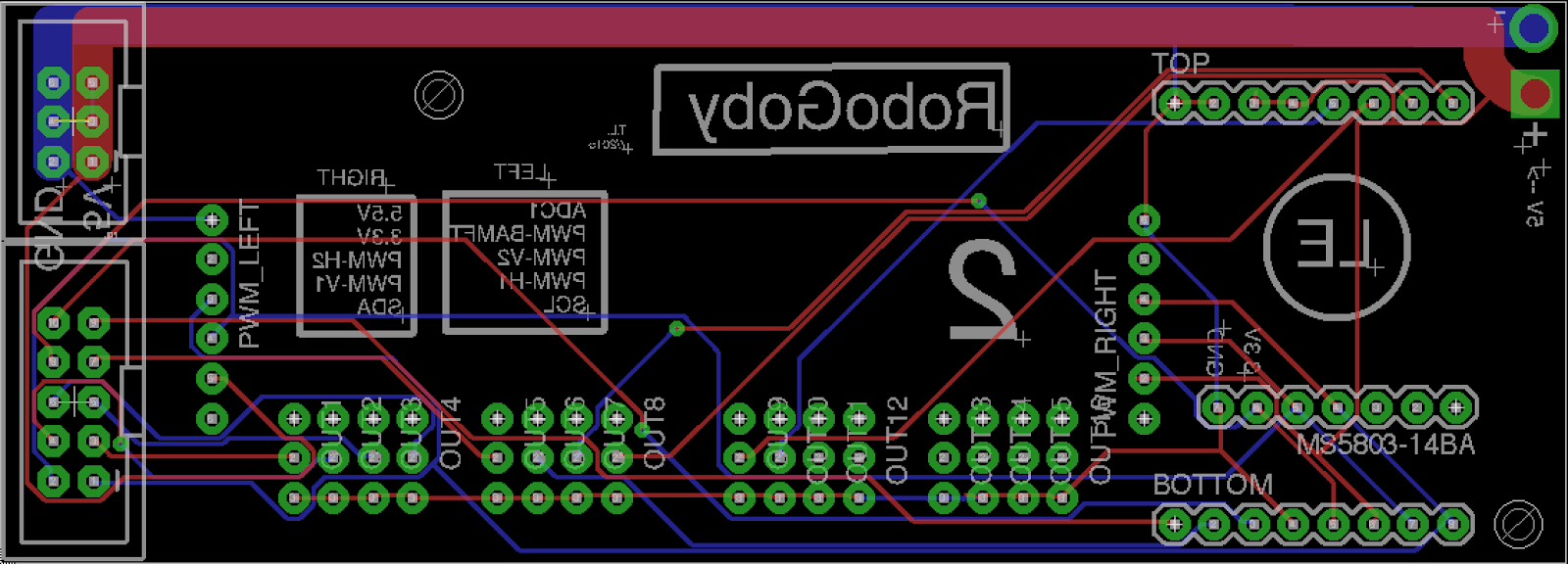
PCB3 - ESC PCB
The last PCB we designed is our "ESC PCB". This PCB has a few key functions. It is used to route the PWM input to the motor controllers and also utilize the 5v output from the ESCs onboard BEC. It also houses the current sensors for each of our motors as well as a humidity and temperature sensors. This PCB is not stacked, but sends power and receives data instructions via the two ribbon cables. An image of the Eagle
 |
| PCB3 (.brd file) |
Board Layout
In order to layout the pins on our boards and figure out the size requirements we used SolidWords. We made designs for each of the PCBs and holes where each of the sensors were going to go. After laying everything out in SolidWorks transferring the PCB to Eagle was easy – we just had to steal the dimensions from solid works and then route all of our connections. Rough pictures (not 100% accurate – screw terminals were reversed) of the CAD are below:
 |
| Stack PCB1 and PCB2 |
 |
| PCB3 |
The finished boards will be arriving soon so stay tuned for a post about PCB construction!