This communication protocol is used for easy, three wire connection between devices. The bus is comprised of Ground, SDA (Serial Data Line), and SCL (Serial Clock Line). The master node on the bus generates a clock and initiates the communication with the slave. Likewise, the slave node receives the clock and responds when addressed by the master. In our case, the Arduino is the slave while the Raspberry Pi is the master.
Software:
Software:
- Arduino IDE (native Wire library)
- Pi4j.com
- Files found in "i2c Communication" folder here
Hardware:
- Raspberry Pi Rev B
- Arduino Uno and Arduino Mega
- Connector cables
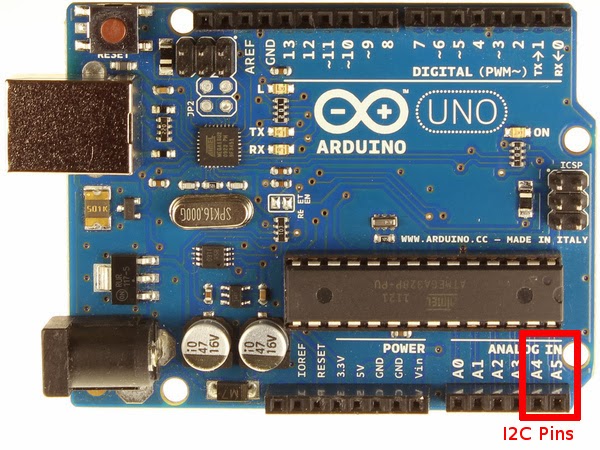
The setup used in this tutorial connects the Raspberry Pi and an Arduino on an I2C bus. Below is an image of the SDA and SCL pins on the Raspberry Pi's GPIO setup and Arduino Uno (A4 & A5):

After connecting the correct pins (don't forget ground!), setup i2c between the Pi and Arduino using these quick steps:
1. Comment out (#) the i2c option (and SPI too) on the Pi's blacklist:


2. Add i2c to /dev/modules


3. Now you can download the i2c-tools needed for debugging:

4. Finally, make sure to add "pi" to the user list unless you want to run your commands using SUDO.

5. Add the .jar files found on Pi4J's download page to the Pi's Java PATH (this will allow you to run the file using java -jar) and as an external library in Eclipse. To add pi4j-core.jar to your Pi, move it from its temporary location to the following location (/usr/lib/jvm..../lib):

6. Download the Java code pictured below. The code can be found in the folder mentioned in the software section above. The highlighted sections below show that the Pi first joins the i2c bus, then locates the Arduino with address 4, and finally reads a set buffer of size 2 from the "slave". For more information on the specific Pi4J methods and implementation check out this site.
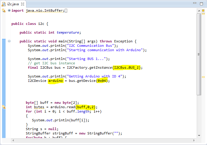
7. You are now finished loading the i2c kernel on the Raspberry Pi. Upload the code from the folder in the downloads sections (.ino file), although the code below is complete and ready for use.

8. Attach the Arduino to power and type in the following command on the Pi. You should see this table below. The Arduino should be recognized as the 0x04 device on the bus (the command for the RevA RPi would switch from a 1 to 0 after -y).

9. Finally, run the .jar file called i2c-temp.jar on the Raspberry Pi (this file will reads two bytes from the Arduino). You will see the same two bytes on the Pi 's terminal. These should be the same numbers you send from the Arduino. An image of the result is below (please disregard the J5 at the bottom of the image):

As we said above, i2c communication not only has the benefit of using only three wires, but it is able to connect more than 127 devices to the Pi at once.
=============
The Arduino code used above will be modified in the future to transfer depth, temperature, and various other readings to the Pi using this circuitry. Please note that Pi4J using the Arduino as a slave on the i2c bus is far from perfect – we ran into many problems testing this over the past week. Some of our findings (inadequacies) can be found in the Arduino (.ino) file on the downloads page we provided above.
Fichero java esta en .jar
ReplyDelete