We decided to test these motors for 2 major reasons. For one, the out-runner brushless motors have high tork for their size. Secondly, brushless motors are waterproof (if the wires are sealed directly) and therefore we do not need to build a waterproof container for them. Below are the steps we used to initialize our ESCs to use the brushless motors.
Hardware:
- 30A ESC controller w/ reverse
- Brushless motor
- Battery (we used a 12v marine battery)
- Breadboard
- 3-wire Analog Dial
Software:
- ServoBlaster
- Arduino IDE
- Arduino code (in the Arduino - Servo file)
Raspberry Pi
1. Download ServoBlaster using git:
2. Install the ServoBlaster module kernel:
3. Make the ServoBlaster nod:
4. Know you can echo commands to the /dev/servoblaster file (echo "5=150" > /dev/servoblaster). Check out the README from the ServoBlaster link above. Use this image to help you attach the wires to the correct spot on the GPIO pins (make sure to only use ground and data):
 |
| RPi revision #2 |
5. To use the ESC, first fasten the motors to something (like a piece of wood) and attach the ESC. Then cut the R/C receiver and peel off the black and white wires (leave the red one alone). Twist the data and ground wires from the ESC and Pi together. It should now looking something like this:
 |
| Brushless Motor |
 |
| 30A ESC w/Radio output |
6. Next, set ServoBlaster to neutral by sending this command:
7. Turn on the ESC and wait for a few short beeps. This means that the controller has detected the neutral signal. Once you've done this you can set the max and min speeds as well as braking power using the manual that came with your motor (if you have a similar LED programmable board to the one we have).
Arduino
The Arduino setup and code we used is based off of this tutorial.
1. Download the latest Arduino IDE and the Arduino Brushless ESC code.
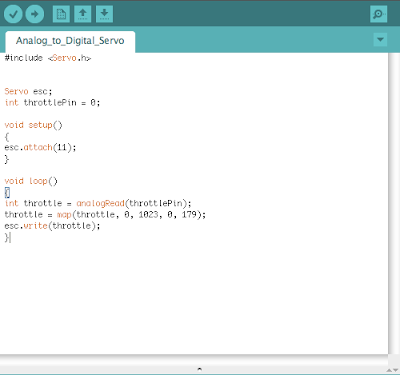
2. Using the analog dial, breadboard, ESC, and Arduino wire them as follows (and do not plug in the 5v ESC wire to the Arduino!!...if both the USB and 5v from the ESC are used you will fry the Arduino). This code allows the Arduino to take the analog voltage variation from the dial and convert it to digital PWM signals which then control the ESC.
3. To program the ESC this way, find the neutral value of your controller (using a volt meter measuring from ground to digital PWM) and then follow the directions in the manual provided with your specific controller. Also make sure to have the correct pin values in your Arduino code (this gets a lot of people) and triple check your breadboard connections (this got us!). Here is an example of the code:
Note: ServoBlaster on the Raspberry Pi is very reliable and works every time. The Arduino not so much...you might have to play around with it a little bit (it has a hard time finding neutral and the Arduino may not read the full range of the dial). Don't get discouraged though – it will work eventually.


No comments:
Post a Comment