After going through a lot of trouble trying to get Sabertooth 2x12 R/C motor controller working with the GPIO (General Purpose Input/Output) pins on the Raspberry Pi, we decided to use a basic motor controller from amazon (found here). The controller is pictured below. It has a simple dial (up to 12v) and is attached to a battery for use in our testing tank (motor controller on far right).
Testing tank (motor controller on far right)
|
After our testing was completed we took off the dial and attached the wires to the Pi. Soon after we had a motor controller which was capable of being turned on and off using the command line. To do this you can follow the steps below. First though, we need to explain exactly how this motor controller works.
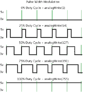
Many motor controllers are attached to power and to a speed controller which has three wires – data, power, and ground. The speed controller can either be a dial, a lever, a computer, etc. The job of the speed controller is to vary of the Pulse Width Modulation signals (PWM signals) going into the motor controller. The duty cycle is how the pulse sizes are defined. They are measured in percentage which relates directly to the speed if the motor.
PWM Duty Cycle
|
Before jumping directly into the project we did some research on the different types of software/commands used to vary the PWM signals from the Raspberry Pi. We ended up finding a very reliable code which is capable of handling up to 8 controllers at once! It's called Pi-Blaster which is an updated version of ServoBlaster** and capable of controlling larger motors. The steps to install this software on the Pi are below. You can also follow the easy instillation process in Pi-Blaster link above.
1. Update Raspbian for good measure.
2. Get the source code using this git command:
3. Build it and then set it up to start on boot.
Now follow these quick steps to successfully attach the motor controller (we used) to the Raspberry Pi. The setup should be similar on any other device as long as it uses the same 1 data-wire setup.
1. Cut three wires – 1 red, 1 black, and 1 green.
2. Replace the dial controller with the wires cut above. It should look like the picture below:
3-wires attached on the left of the picture
|
3. Now attach the red wire to the 5v output on the Pi and the black ground. A picture of the GPIO setup on the Pi is below (Revision 2 which is Pi version B – look for revision 1 on the internet if you have a first generation RPi):
Revision 2
|
What our RPi 26 pin connector looks like (we would recommend using a ribbon cable/pin extension as not to ruin the Pi's pins):
Data, Power, and Ground attached to RPi
|
4. The green wire has to go on one of the following pins. Using this chart and the diagram above attach the green wire to the Pi:
5. After connecting all of the wires, attach the motor and power supply to the motor controller.
6. Write these command into terminal. They forward the commands to /dev/pi-blaster which then uses them to send PWM signals.
- To completely turn on Channel2(GPIO 18) 100%:
- To turn on Channel2 35%:
- To turn off Channel2 (0%):
Here is a video of our motor controller and motor using these commands:
That's it! You can now use these commands to vary the speed of your motors for any type of project! Stay updated on our blog to learn how to write a simple program in which we will use arrow keys to speed up/slow down motors.


please message me on facebook. i have a question about raspberry pi and sabertooth 2x25
ReplyDeleteTheGoodRobot.com is my fb page
if you reply here, do it on this comment because i check marked "notify me" when you write back. or just message me on fb
Delete