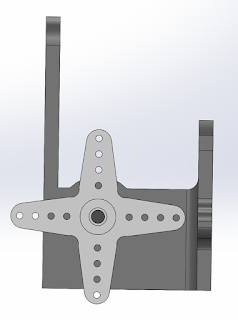
The camera mount is made of four distinct pieces. There are two parts that hold the camera system in place, the servomotor motor mount and the bearing mount. The other two parts are the shaft and camera mount.
Below are the two side mounts. One side holds the servo motor and the other side acts as a bearing for the shaft which the camera is mounted to.
 |
| Servomotor Mount |
 |
| Shaft Bearing Mount |
We thought about putting a bushing in the hole instead of using the plastic support as a bearing, but we decided against it as the printer plastic is quite slick.
The third part is the shaft on which the camera rotates. The white piece on the end which attaches to the servo motor is a servo horn that comes packaged with the servo motor. The shaft has a large mount connected to it. This makes a "shaft extension" that has three main functions. First, it has holes which attach it to the white piece on the servo, holding the piece to the shaft. Second, the two holes on the bottom are to hold the camera case to the shaft. Third the four top holes and two half circles are a LIDAR mount (see below).
 |
| Shaft Side View |
 |
| Shaft Isometric View |
The final part of the camera mount is the camera case itself. The case will be filled with epoxy, which is why there is a front as it makes it easier to keep epoxy off of the lens. The hole in the top is for the USB cable, which we are using to communicate with the camera board.
 |
| Camera Case |
Integrated LIDAR Mount
Our front facing LIDAR is attached to the camera system so that they tilt in conjunction with each other. As mentioned above the mount is part of the camera shaft mount. It consists of four bolt holes to attach the sensor and two arcs for the circular "lenses" to rest on.
 |
| LIDAR in Mount |
Entire Camera & LIDAR Mount
--------------------------------------------------------------------------------------------------------------------------
UPDATE (7/13/2015): A New Camera Mount
After finalizing the design for out lighting system we needed to change a few things on the camera mount (but kept the sensor mount). Using the same basic idea we consolidated the pieces from the previous mount and cleaned things up a bit.We kept the same basic design for the shaft mount as above, but added a camera case to it. While this definitely stressed the 3D printer to its maximum ability, we thought it was important for a simpler design. This piece is mounted to a rotating shaft (controlled by a servo) and then mounts to the front facing LiDAR, the stereoscopic camera, and the IR LEDs. It can be considered one of the most important parts of the sub design. An image of the mount is below:
 |
| Camera + LiDAR + LED Mount |
The face piece to this design is also very important because it holds LED mounts. This piece is made out of Delrin for extra stability. The large holes in the plastic are for the cameras, the medium sizes holes are for 3mm bolts, and the small holes are for 2mm bolts.
 |
| Cam Cover and LED Mount |
We also changed the Servo Mount and the Shaft Bearing Mount. These new mounts were incorporated into the half-circular mounts that replaced the LED heat-sinks (changed with lighting design change). The updated mounts are pictured below. The one on the right is the servo mount as well as the right hand cover. The left has the shaft bushing and acts as the left side cover.
 |
Then using these mounts and putting everything together we get the final assembly for the front of the sub:
 |
| Front Mounts&Sensors |
As you can see this design not only has less pieces than the other design, but it looks much better overall.
--------------------------------------------------------------------------------------------------------------------------
Front Sensor Package
Just behind the camera and in front of the foremost thruster we put a pack of sensors. The pack consists of a depth sensor, an IMU and a downward facing LIDAR. The IMU is on the central axis of the sub and the depth sensor is just in front of it - there is also a track we will use to route wires. The hole and bolts for the LIDAR are on the left side of the sub (right side of the image). The LIDAR sticks out the bottom of the mount so that it is flush with the bottom of the submersible body.
 |
| Front Sensor Package |


Wow, what a blog! I mean, you just have so much Play Online Casino guts to go ahead and tell it like it is. You're what blogging needs, an open minded superhero who inst afraid to tell it like it is. This is definitely something people need to be up on. Good luck in the future, man
ReplyDelete